Sidebar 4: Measurements
I measured the performance of the Miyajima Wo-1 with my Audio Precision SYS2722 system. When I connected the preamplifier's output to the analyzer and switched it on, the Audio Precision's gain-ranging kept changing. Ken Micallef had told me that he had heard "pops" when he turned the preamplifier on, likely the result of a DC voltage somewhere in the audio circuit. An obvious place to look would be on the wiper of a conventional volume control potentiometer; however, I would not have thought the Wo-1's unusual "shunt" switched-resistor volume control would suffer from this problem.
I powered down the Miyajima, connected a Fluke DC voltmeter to the left channel's output, and turned the preamplifier back on, leaving the volume control set to its minimum. The voltmeter immediately registered a DC offset of >30V, which slowly declined, the DC voltage dissipating, perhaps across the voltmeter's very high input resistance, perhaps via some other route. I repeated the procedure with the Wo-1 connected to a 100k ohm load. Again when I powered up, there was an initial DC offset of >30V, but this time it declined to 1v after 20s and to 10mV after 35s. After that, it varied slowly between –10mV and +2mV before reaching 0V a few minutes later. With a 10k ohm load, which is a typical power amplifier input impedance, the DC offset declined to 1V after 10s and to 5mV after 20s. (With the lower resistance, the DC discharge current is higher; therefore it takes less time for the DC voltage to dissipate.)
This behavior is presumably due to the tubes taking time to reach their stable operating condition. However, it behooves owners of the Wo-1 to wait to turn on their power amplifiers until the preamplifier has been on for a few minutes and the DC offset has dissipated. If the power amplifier is capacitor-coupled, which I understand KM's amplifiers to be, there will indeed be audible "pops" when the preamp is turned on, but otherwise there won't be any harm. With a modern direct-coupled solid state amplifier, that initial DC offset will destroy the loudspeakers' woofers.
That investigation over, I started measuring the Miyajima Wo-1's performance via its Aux line inputs. The preamplifier preserved absolute polarity (ie, was noninverting). The maximum gain with the gain switch in its default setting, as used by KM, was 31.55dB, left channel, and 31.32dB, right. Switched to "Gain-A," the maximum gain was 9.4dB; in "Gain-B" it was –0.7dB.


Turning to the two moving magnet–compatible inputs, these preserved absolute polarity and both offered a maximum gain of 60.1dB at the preamplifier's main outputs, 28.35dB at the Rec output. Because of the line stage's relatively high levels of noise and distortion, as well as the fact that the left channel's output gain had once again dropped by 3.5dB, I tested the phono stage's performance at the Rec output.
Phono input A has a fixed impedance of 47k ohms; I measured 43k ohms at 20Hz, 45k ohms at 1kHz, and 40k ohms at 20kHz. Phono input B can have its impedance switched to several values between 6020 ohms and 100k ohms. The measured impedances were all close to the indicated values.


The problems I encountered with the left channel's noise proved to be the result of an aging small signal tube; when I swapped tubes, left to right and right to left, the excess noise switched channels. The frequency response differences, distortion levels, and clipping behavior were unaffected. I did not see the drop in gain I witnessed earlier after I swapped the tubes, but it too is likely a result of a suboptimal tube.
I am sure that there was no damage due to the journey from KM's place to mine, and while there was no shipping box, KM had carefully wrapped the preamp in bubble-wrap before I picked the preamplifier up from him. But I must caution potential purchasers that if they use a direct-coupled solid state amplifier, they must never turn the Miyajima Wo-1 on with the amplifier already powered up. (Turning on the power amplifier after the preamplifier is always good practice.)—John Atkinson
Footnote 1: I swapped all the tubes between the channels. The noise floor was now higher in the right channel than in the left.
Fig.1 Miyajima Wo-1, line input frequency response at 2V into 100k ohms (with volume control set to maximum (left channel blue, right red) and to –24.8dB (left green, right gray, offset by –1dB) (0.5dB/vertical div.)
The Wo-1's Aux input impedance was a very high 129k ohms at 20Hz, 122k ohms at 1kHz, and 89k ohms at 20kHz. The CD input impedance was even higher, at 142k ohms at 20Hz, 168k ohms at 1kHz, and 107k ohms at 20kHz. Even with the cathode-follower output stage, the preamplifier's source impedance was relatively high, ranging from 3550 ohms at 20Hz to 1167 ohms at 20kHz. The preamplifier's frequency response was down by 3dB just below 200kHz (fig.1). However, with the volume control set to its maximum, the left channel (blue trace) was 0.5dB higher than the right (red trace). The channel matching was better with the volume control set to the 12:00 position, corresponding to –24.8dB (green and gray traces). At both settings, the low frequencies rolled off by 3dB at 10Hz.
The Miyajima preamp's channel separation was good below 2kHz, at >70dB in both directions, but it decreased to 50dB at the top of the audioband (not shown). I started to examine the level of the noise in the preamplifier's output but encountered another problem. The left channel's gain suddenly dropped 3.5dB and its noisefloor rose by 20dB. I removed the Wo-1's top cover and checked that all the tubes were correctly seated. I then used the front-panel meter to check that the tubes' zero balance was 50mV in both channels, as advised in the manual. They were. I powered down the Miyajima and left it unpowered overnight before resuming the measurements.
Fig.2 Miyajima Wo-1, line input, spectrum of 1kHz sinewave, DC–1kHz, at 2V into 100k ohms with volume control set to –11.5dB (left channel blue, right red) (linear frequency scale).
The two channels' gains were now the same as they had been when I started the testing, though the left channel's noisefloor was still higher in level than the right channel's (footnote 1). With the volume control set to its maximum, the wideband, unweighted signal/noise ratio, measured with the inputs shorted to ground, was 27.8dB in the left channel, 49.1dB in the right, both ratios ref. 1V output. Restricting the measurement bandwidth to the audioband increased the S/N ratio to 29.1dB, left, 52.8dB, right, while switching an A-weighting filter into circuit improved those ratios to 36.3dB and 63.6dB, respectively. The level of the noisefloor was related to the volume control setting and the setting of the gain switch. Gain-A improved the S/N ratios by 20dB, Gain-B by 32dB. Reducing the output level by 20dB with the volume control lowered the levels of the noise in both channels by the same amount. As KM used the Wo-1's highest gain condition, he would have used the volume control at a relatively low setting, which presumably is why he didn't hear noise in the left channel. Fig.2 shows the low-frequency spectra with the volume control set to –11.5dB. AC-related spuriae are present at close to –80dB ref. 2V in both channels, but the low-frequency random noise level was 10–20dB higher in the left channel (blue trace) than the right (red trace).
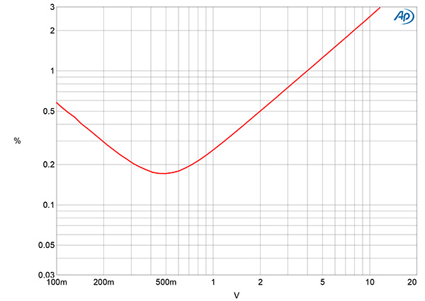
Fig.3 Miyajima Wo-1, line input, right channel, distortion (%) vs 1kHz output voltage into 100k ohms.
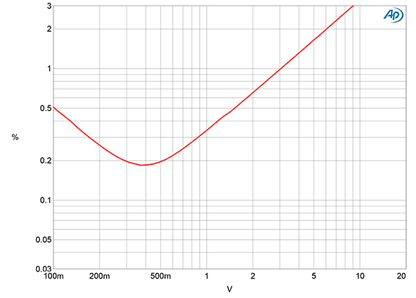
Fig.4 Miyajima Wo-1, line input, right channel, distortion (%) vs 1kHz output voltage into 10k ohms.
Figs.3 and 4 respectively show how the THD+noise percentage in the right channel varied with voltage into 100k ohms and 10k ohms. The downward slope of the traces below 500mV in these graphs is due to the reading being dominated by noise. Actual distortion starts to rise above the noisefloor above that voltage and the THD+N reaches 1%—our usual definition of clipping—at 4V into 100k ohms and 3V into 10k ohms. (I haven't shown how the THD+N varies with voltage into 600 ohms, as the Wo-1 clipped at just 500mV into this punishing load.)
Fig.5 Miyajima Wo-1, line input, distortion (%) vs frequency at 1V into 100k ohms (left channel blue, right red) and 10k ohms (right channel gray).
Fig.6 Miyajima Wo-1, line input, spectrum of 50Hz sinewave, DC–1kHz, at 1V into 100k ohms with volume control set to –11.5dB (left channel blue, right red; linear frequency scale).
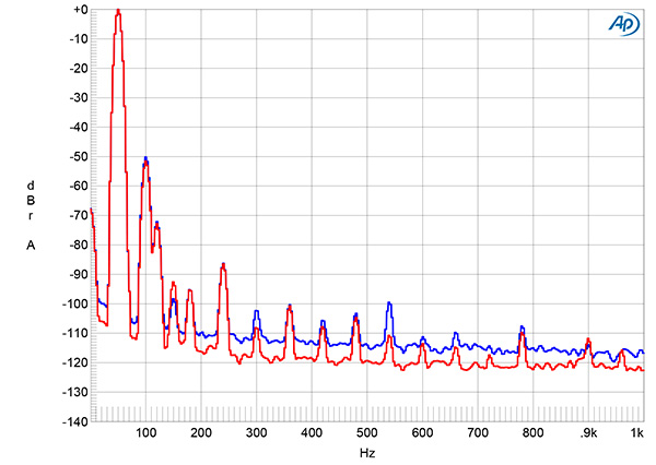
Fig.7 Miyajima Wo-1, line input, HF intermodulation spectrum, DC–30kHz, 19+20kHz at 1V into 100k ohms with volume control set to –11.5dB (left channel blue, right red; linear frequency scale).
Below actual clipping, the THD+N percentage against frequency at 1V into both 100k ohms and 10kHz is relatively high, at around 0.3% (fig.5), but it doesn't change significantly with frequency. The Miyajima's distortion signature is dominated by the second harmonic (fig.6). This will add warmth to the preamplifier's sonic character but is subjectively benign unless it is accompanied by high levels of intermodulation distortion. When I tested for intermodulation distortion with an equal mix of 19kHz and 20kHz tones at a peak level of 1V into 100k ohms, the second-order difference product at 1kHz lay at a moderately low –56dB (0.15%). However, the spectrum of the Wo-1's output with this signal (fig.7) is affected by a multitude of supply-related products. Though these all lie at a low level, I have never encountered anything like this with other preamplifiers. It is difficult to know whether, and how, they will affect the sound.
Fig.8 Miyajima Wo-1, phono input, response with RIAA correction into 100k ohms (left channel blue, right red) (1dB/vertical div.).
The Wo-1's RIAA equalization (fig.8) had a significant dip in the midrange, though the channel matching was excellent overall. The equalization error rose with increasing frequency above 10kHz, which suggests that the Wo-1 offers the so-called Neumann 4th pole. The phono stage's channel separation (not shown) was >70dB in both directions across most of the audioband but decreased to 55dB below 100Hz.
Fig.9 Miyajima Wo-1, phono input, spectrum, DC–1kHz, at Rec output ref. 5mV input (left channel blue, right red, linear frequency scale, 20dB/vertical div.).
The Miyajima's unweighted, wideband S/N ratio, measured with the input shorted to ground, was a moderate 45.1dB, left, and 38.6dB, right, ref. 1kHz at 5mV. Restricting the measurement bandwidth to 22Hz–22kHz increased these ratios to 48.7dB in the left channel, 41.1dB in the right. The A-weighted ratios were 64.4dB, left, and 59.5dB, right. Spectral analysis of the Miyajima phono stage's low-frequency noisefloor revealed that the random noise components were relatively high in level (fig.9).
Fig.10 Miyajima Wo-1, phono input, spectrum of 1kHz sinewave, DC–10kHz, at Rec output into 100k ohms for 20mV input (left channel blue, right red, linear frequency scale).
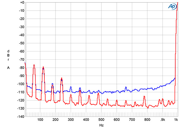
The Wo-1's phono overload margin (ref. 1kHz at the standard MM level of 5mV) was an extraordinary 40dB at 20Hz and 55dB at 1kHz. I couldn't measure the overload margin at 20kHz because the necessary input voltage exceeded the Audio Precision's 15V maximum output. It must have been at least 48dB. With a 1kHz signal at a level 12dB higher than 5mV, the Miyajima's phono input offered very low distortion (fig.10). The only distortion harmonic that can be seen above the noisefloor is the second, at –90dB (0.003%). The Wo-1's phono input also offered a low level of intermodulation distortion. With a 1V peak input signal comprising equal levels of 19kHz and 20kHz tones, the second-order difference product lay at just –80dB (0.01%, fig.11).
Fig.11 Miyajima Wo-1, phono input, spectrum of 1kHz sinewave, DC–10kHz, at Rec output into 100k ohms for 20mV input (left channel blue, right red, linear frequency scale).
The Miyajima Wo-1's measured performance is a mixed bag. While its phono stage has unflat RIAA equalization and a relatively high level of random noise, it features extremely low distortion and its overload margins are the highest I have ever found. It will work well with high-output moving magnet cartridges and high-gain moving coil head amplifiers. By contrast, the Wo-1's line stage has a high level of primary second-harmonic distortion and has problems driving loads below 10k ohms.
Footnote 1: I swapped all the tubes between the channels. The noise floor was now higher in the right channel than in the left.