Sidebar 3: Measurements
I performed measurements on the Roksan Attessa with my Audio Precision SYS2722 system. I preconditioned the amplifier by operating it at 1/8 power into 8 ohms for 30 minutes. At the end of that time, the top panel's temperature was 108.4°F/42.4°C and that of the grille over the heatsinks almost too hot to touch, at 134.4°F/55.9°C. The Attessa needs sufficient ventilation.
Looking first at the line-level analog "Variable Input" and with the sensitivity set to "Low" with the MaestroUnite app, the Roksan Attessa's maximum voltage gain at 1kHz was 34.9dB from the loudspeaker output into 8 ohms, 5.85dB from the Pre output, and 11.85dB from the headphone output with the sensitivity set to "Mid." The amplifier preserved absolute polarity, ie, it was noninverting from its loudspeaker, headphone, and Pre outputs. The input impedance was 25k ohms at 20Hz and 1kHz and 23.6k ohms at 20kHz.
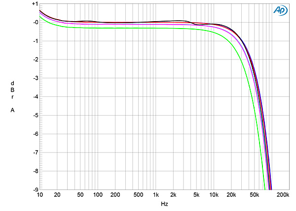
The headphone output's source impedance was a usefully low 6 ohms from 20Hz to 20kHz. From the Pre output the impedance was 23 ohms, again at all audio frequencies. The loudspeaker output impedance was a very low 0.09 ohms at low and middle frequencies, increasing very slightly to 0.17 ohms at the top of the audioband. The variation in the Roksan amplifier's small-signal frequency response with our standard simulated loudspeaker was just ±0.1dB (fig.1, gray trace). Into resistive loads (fig.1, blue, red, cyan, magenta, and green traces), the Attessa's frequency response rolled off above the audioband. The fastest rolloff was into 2 ohms (green trace), the output being down by 3dB at 39kHz. There is the beginning of a boost at frequencies below 20Hz in this graph; the measurements in our sister magazine Hi-Fi News indicated that this boost reached +9.2dB at 3Hz.

 The Roksan's MM-compatible phono input preserved absolute polarity at all three outputs. The phono input's audioband RIAA correction was superbly accurate (fig.20), though with a slight rise in the very low bass. The input impedance measured 45k ohms at 20Hz and 1kHz, dropping slightly to 40k ohms at 20kHz. The maximum gain at 1kHz, with the sensitivity set to "Mid" with the MaestroUnite app, was 55.5dB at the Pre output, 61.4dB at the headphone output, and 84.5dB at the loudspeaker outputs. I performed all the subsequent testing using the headphone output and, other than S/N ratio, with the volume control set to –20dB to avoid clipping the output.
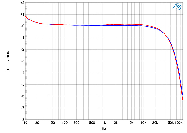
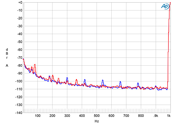
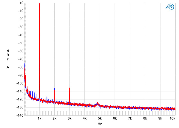
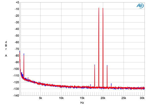
Fig.1 Roksan Attessa, frequency response at 2.83V into: simulated loudspeaker load (gray), 8 ohms (left channel blue, right red), 4 ohms (left cyan, right magenta), and 2 ohms (green) (1dB/vertical div.).
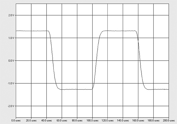
Fig.1 was taken with the volume control set to its maximum; the excellent channel matching was preserved at lower settings of the control with all three outputs. I found no overshoot or ringing with the Attessa's reproduction of a 10kHz squarewave (fig.2). The Attessa's channel separation (not shown) was 80dB in both directions below 3kHz, decreasing slightly to 68dB at 20kHz.
Fig.2 Roksan Attessa, small-signal 10kHz squarewave into 8 ohms.
The unweighted, wideband signal/noise ratio (ref. 1W into 8 ohms), taken with the inputs shorted to ground and the volume control set to its maximum, was 66.5dB (average of the two channels), improving to 71.7dB, left, and 68.4dB, right, when the measurement bandwidth was restricted to 22Hz–22kHz, and by another 2.4dB when A-weighted. Spectral analysis of the low-frequency noisefloor while the Roksan amplifier drove a 1kHz tone at 1Wpc into 8 ohms with the volume control set to the maximum (fig.3) revealed the presence of AC-related spuriae at 60Hz and its odd- and even-order harmonics. These were higher in the right channel (red trace) than the left (blue), correlating with the different S/N ratios in the two channels. The levels of these spuriae didn't change when I repeated the analysis with the volume control set to –12dB, though the level of random noise dropped by the same 12dB.
Fig.3 Roksan Attessa, spectrum of 1kHz sinewave, DC–1kHz, at 1Wpc into 8 ohms with volume control set to its maximum (left channel blue, right red) (linear frequency scale).
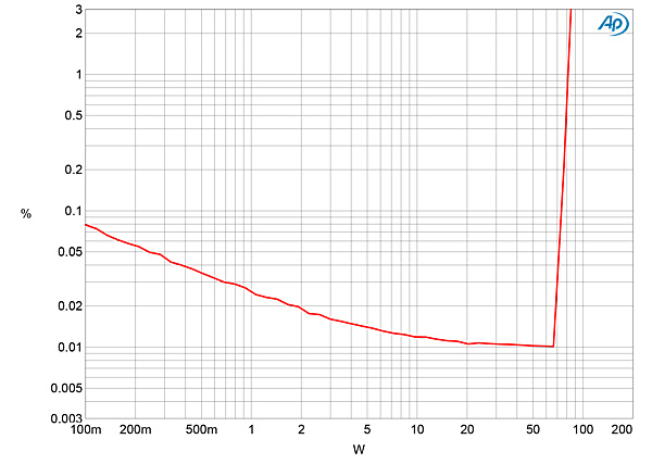
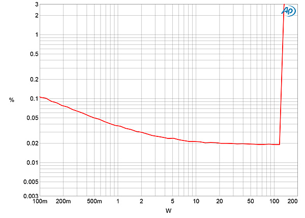
Roksan specifies the Attessa's maximum power as 80Wpc into 8 ohms (19dBW) and 130Wpc into 4 ohms (18.13dBW). With clipping defined as being when the THD+noise reaches 1%, I measured clipping powers of 80Wpc into 8 ohms (19dBW, fig.4) and 128Wpc into 4 ohms (18.06dBW, fig.5) with both channels driven. (The AC wall voltage had dropped from 119.3V with the Attessa idling to 118.5V with it clipping into 4 ohms.) The shape of the traces in these graphs suggests that the actual distortion lies beneath the noisefloor below clipping.
Fig.4 Roksan Attessa, distortion (%) vs 1kHz continuous output power into 8 ohms.
Fig.5 Roksan Attessa, distortion (%) vs 1kHz continuous output power into 4 ohms.
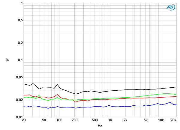
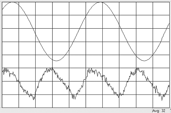
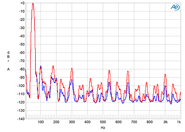
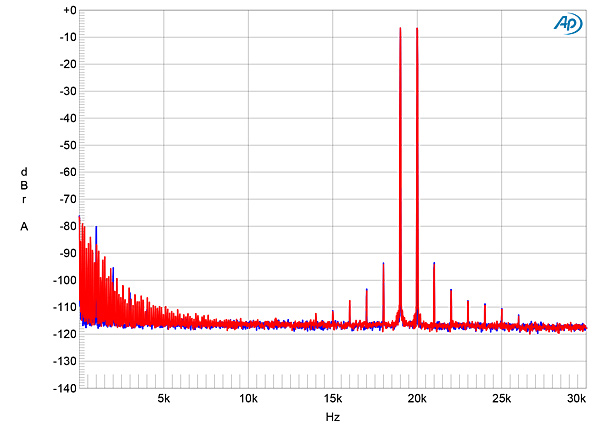
Fig.6 shows how the percentage of THD+N in both channels varied with frequency into 8 and 4 ohms at 12.64V, which is equivalent to 20W into 8 ohms (blue and red traces) and 40W into 4 ohms (green and gray traces). The THD+N was very low into both impedances, though a little higher in the right channel (red, gray) than the left (blue, green). The distortion waveform was predominantly the subjectively innocuous second harmonic (fig.7), which lay close to the level of the AC supply–related spuriae (fig.8). Intermodulation distortion was also very low in level (fig.9).
Fig.6 Roksan Attessa, THD+N (%) vs frequency at 12.64V into 8 ohms (left channel blue, right red), 4 ohms (left green, right gray).
Fig.7 Roksan Attessa, left channel, 1kHz waveform at 20W into 8 ohms, 0.04% THD+N (top); distortion and noise waveform with fundamental notched out (bottom, not to scale).
Fig.8 Roksan Attessa, spectrum of 50Hz sinewave, DC–1kHz, at 40Wpc into 4 ohms (left channel blue, right red; linear frequency scale).
Fig.9 Roksan Attessa, HF intermodulation spectrum, DC–30kHz, 19+20kHz at 40Wpc peak into 4 ohms (left channel blue, right red; linear frequency scale).
Turning to the digital inputs, the coaxial S/PDIF input accepted data sampled at all rates up to 192kHz; TosLink was restricted to 96kHz data. All the digital inputs preserved absolute polarity. With the volume control set to its maximum, data representing a 1kHz tone at –20dBFS resulted in a level of 819.2mV at the headphone output, 11.47V at the speaker outputs. (The latter suggests that the digital stage has about 13dB too much gain.) All the following measurements were performed at the headphone output.
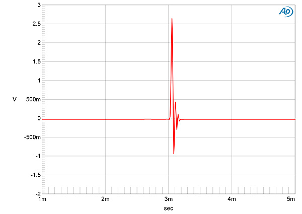
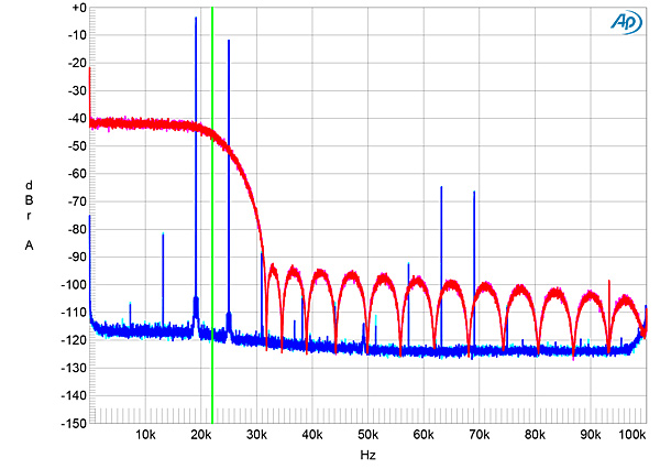
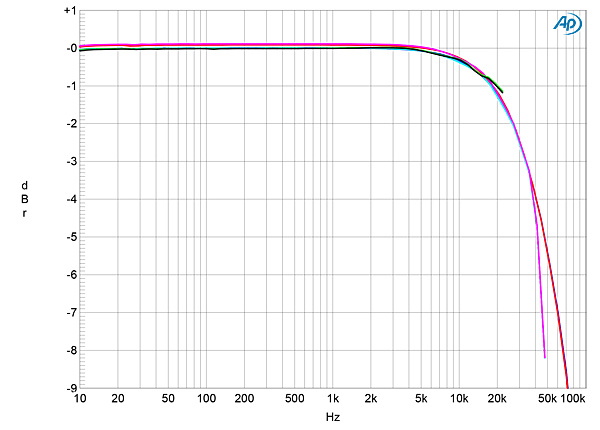
Fig.10 shows the Attessa's impulse response with 44.1kHz data. It is typical of a short, minimum-phase reconstruction filter, with a small amount of ringing following the single full-scale sample. With 44.1kHz white-noise data (fig.11, magenta and red traces), the filter rolled off slowly above the audioband, not reaching full stop-band attenuation until 31kHz, but with then a scalloped noisefloor. With a 19.1kHz tone at –3dBFS (cyan, blue), the slow rolloff means that the aliased image at 25kHz is only suppressed by 9dB, and other, lower-level aliased products can be seen both in the audioband and between 60kHz and 70kHz. The harmonics associated with the 19.1kHz tone are all very low in level, however. The Roksan's frequency responses with data sampled at 44.1, 96, and 192kHz (fig.12) all followed the same basic shape, with a 1dB rolloff at 20kHz.
Fig.10 Roksan Attessa, impulse response (one sample at 0dBFS, 44.1kHz sampling, 4ms time window).
Fig.11 Roksan Attessa, wideband spectrum of white noise at –4dBFS (left channel red, right magenta) and 19.1kHz tone at –3dBFS (left blue, right cyan) into 100k ohms with data sampled at 44.1kHz (20dB/vertical div.).
Fig.12 Roksan Attessa, frequency response at –12dBFS into 100k ohms with data sampled at: 44.1kHz (left channel green, right gray), 96kHz (left cyan, right magenta), and 192kHz (left blue, right red) (1dB/vertical div.).
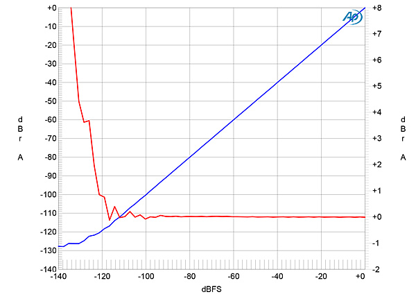
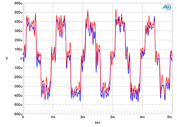
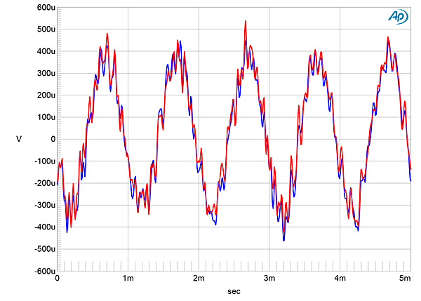
The red trace in fig.13 plots the error in the analog output level as a 24-bit, 1kHz digital tone steps down from 0dBFS to –140dBFS. The amplitude error is negligible until the signal lies below –120dBFS. An increase in bit depth from 16 to 24 with dithered data representing a 1kHz tone at –90dBFS (fig.14) dropped the level of the Attessa's noisefloor by 12dB, which implies a DAC resolution of around 18 bits. With undithered data representing a tone at exactly –90.31dBFS, the waveform was symmetrical, with the three DC voltage levels described by the data cleanly resolved (fig.15). Repeating the measurement with undithered 24-bit data gave a well-formed if rather noisy sinewave (fig.16).
Fig.13 Roksan Attessa, left channel, 1kHz output level vs 24-bit data level in dBFS (blue, 20dB/vertical div.); linearity error (red, 1dB/small vertical div.).
Fig.14 Roksan Attessa, spectrum with noise and spuriae of dithered 1kHz tone at –90dBFS with: 16-bit TosLink data (left channel cyan, right magenta), 24-bit TosLink data (left blue, right red) (20dB/vertical div.).
Fig.15 Roksan Attessa, waveform of undithered 1kHz sinewave at –90.31dBFS, 16-bit data (left channel blue, right red)
Fig.16 Roksan Attessa, waveform of undithered 1kHz sinewave at –90.31dBFS, 24-bit data (left channel blue, right red)
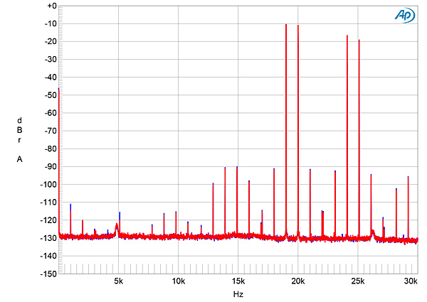
As implied by the blue and cyan traces, in fig.11, harmonic distortion via the digital inputs was very low, the second harmonic of a full-scale 50Hz tone lying at –104dB (0.0006%), left, and –114dB (0.0002%), right (fig.17). With an equal mix of 19kHz and 20kHz tones sampled at 44.1kHz and peaking at 0dBFS, a large number of high-level aliased images were present. Reducing the signal level by 3dB eliminated most of these images, leaving those at 24.1kHz and 25.1kHz the highest in level (fig.18) and all the others at or below –90dBFS.
Fig.17 Roksan Attessa, 24-bit TosLink data, spectrum of 50Hz sinewave, DC–1kHz, at 0dBFS into 100k ohms (left channel blue, right red; linear frequency scale).
Fig.18 Roksan Attessa, 24-bit TosLink data, HF intermodulation spectrum, DC–30kHz, 19+20kHz at –3dBFS into 100k ohms, 44.1kHz data (left channel blue, right red; linear frequency scale).
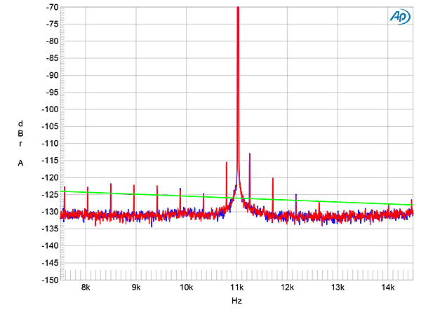
With undithered, 16-bit J-Test optical data, the odd-order harmonics of the undithered Fs/192, LSB-level squarewave mostly lay a little higher than the correct levels, these indicated by the sloping green line in fig.19. While the levels of the sidebands at ±229.6875Hz are much higher, repeating this test with data sent to the Attessa over my network with BluOS lowered these two sidebands by 10dB.
Fig.19 Roksan Attessa, high-resolution jitter spectrum of analog output signal, 11.025kHz at –6dBFS, sampled at 44.1kHz with LSB toggled at 229Hz: 16-bit TosLink data (left channel blue, right red). Center frequency of trace, 11.025kHz; frequency range, ±3.5kHz.
Fig.20 Roksan Attessa, phono input, response with RIAA correction (left channel blue, right red) (1dB/vertical div.).
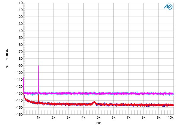
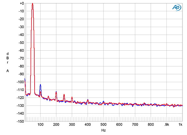
I connected a wire from the Audio Precision's ground terminal to the grounding lug on the Roksan's rear panel to obtain the lowest noise with the phono input. The wideband, unweighted S/N ratio with the inputs shorted to ground and the volume control set to the maximum was a very good 71dB in both channels, ref. 1kHz at 5mV. Restricting the measurement bandwidth to the audioband increased the ratio to 76dB, while an A-weighting filter further increased the ratio to 82.6dB. Spectral analysis of the phono input's low-frequency noisefloor (fig.21) revealed very low levels of random noise and power supply–related spuriae.
Fig.21 Roksan Attessa, MM phono input, spectrum of 1kHz sinewave, DC–1kHz, for 5mV input, measured at headphone output with volume control set to the maximum (left channel blue, right red, linear frequency scale).
The phono input's overload margins, measured at the headphone output and ref. 1kHz at 5mV, were superbly high at 20Hz and 1kHz, at 23.5dB. The margin dropped to a still-good 10.5dB at 20kHz. The phono input's distortion signature was an equal mix of second and third harmonics, both lying at –106dB (0.0005%) with 1kHz at an input level of 20mV (fig.22). The level of the 1kHz difference product with an equal mix of 19 and 20kHz tones (fig.23) was very low, at close to –80dB (0.01%), with the high-order intermodulation products even lower in level.
Fig.22 Roksan Attessa, MM phono input, spectrum of 1kHz sinewave, DC–10kHz, for 20mV input, measured at headphone output with volume control set to –20dB (left channel blue, right red, linear frequency scale).
Fig.23 Roksan Attessa, MM phono input, HF intermodulation spectrum, DC–30kHz, 19+20kHz witht 100mV input (left channel blue, right red; linear frequency scale).
With separates, it is possible for the designers to maximize resolution and minimize noise. With a single-box solution like the Roksan Attessa, it is difficult to do these things, with the current-heavy power supply in such close proximity to the low-level analog and digital decoding stages. However, the Attessa's measured performance, especially that of the low-noise, low-distortion phono input, indicates that the inevitable compromises have been managed well.—John Atkinson