Sidebar 1: Measurements
The Accuphase DC-91 had a maximum output level of 2.64V from the balanced outputs, 2.54V from the single-ended outputs. The output impedance measured a low 49 ohms (balanced) and 52 ohms (unbalanced) at any audio frequency. These low output impedances suggest that the DC-91 will drive any preamplifier and cable with ease, and will not be loaded down by low input impedances. The DC-91 doesn't invert absolute polarity from the single-ended outputs, but the XLR connectors are wired with pin 3 hot—contrary to the AES standard of pin 2 hot. This will cause the DC-91 to invert polarity when connected to pin 2–hot equipment through the balanced connections, even though the processor's polarity switch is set to "positive."
Fig.2 shows the DC-91's frequency response and de-emphasis error. The response is flat, and the de-emphasis tracking is nearly perfect. We can see a very slight level imbalance between the left and right channels. The DC-91's crosstalk performance (fig.3) was excellent, measuring better than 110dB at any audio frequency. At 1kHz, the channel separation was 115dB, which is superb.


 This difference in input word-length becomes an issue only with very-high-quality digital processors. Now that the NPC5842 and Pacific Microsonics PMD100 filters—both of which will pass up to 24-bit data—are appearing in processors, our measurements should include the processor's performance with longer input words. Otherwise, we end up measuring the dither content of the Audio Precision System One's digital signal generator rather than the digital processor under evaluation.
A wideband spectral analysis of a –90dB 5Hz tone (fig.6), made with the Accuphase's dither turned off, reveals the DC-91's very low intrinsic noise floor. The energy peaks at 32kHz, 64kHz, and 96kHz are unusual, almost looking like some form of ripple.
This difference in input word-length becomes an issue only with very-high-quality digital processors. Now that the NPC5842 and Pacific Microsonics PMD100 filters—both of which will pass up to 24-bit data—are appearing in processors, our measurements should include the processor's performance with longer input words. Otherwise, we end up measuring the dither content of the Audio Precision System One's digital signal generator rather than the digital processor under evaluation.
A wideband spectral analysis of a –90dB 5Hz tone (fig.6), made with the Accuphase's dither turned off, reveals the DC-91's very low intrinsic noise floor. The energy peaks at 32kHz, 64kHz, and 96kHz are unusual, almost looking like some form of ripple.


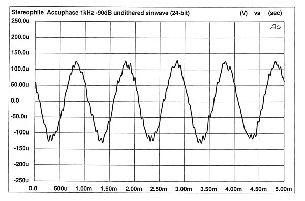


Fig.2 Accuphase DC-91, frequency response (top) and de-emphasis error (bottom) (right channel dashed, 0.5dB/vertical div.).
Fig.3 Accuphase DC-91, R–L crosstalk in balanced mode (L–R dashed, 10dB/vertical div.).
A spectral analysis of the DC-91's output when decoding a 1kHz, –90dB dithered sinewave is shown in fig.4. The noise level is low, and we can see a total absence of power-supply noise in the audio circuitry. Because the DC-91 can accept 20-bit–long words, the apparent noise floor in fig.4 is limited by the dither of the Audio Precision System One's digital-signal generator being set to the 16-bit level. Increasing the output word length to 20 bits and repeating the measurement yielded the plot of fig.5. Note the expanded vertical scale, which now goes to –150dBFS (instead of –130dBFS), needed to show the much lower noise floor. This plot represents the DC-91's true noise floor: it implies close to true 20-bit performance from the Accuphase processor, again with a complete absence of any power-supply artifacts.
Fig.4 Accuphase DC-91, spectrum of dithered 1kHz tone at –90.31dBFS, with noise and spuriae, 16-bit input word length (1/3-octave analysis, right channel dashed).
Fig.5 Accuphase DC-91, spectrum of dithered 1kHz tone at –90.31dBFS, with noise and spuriae, 20-bit input word length (1/3-octave analysis, right channel dashed).
Fig.6 Accuphase DC-91, spectrum of 5Hz tone at –90dB (1/3-octave analysis, right channel dashed).
Fig.7 is the DC-91's linearity, which is among the best we've measured. Even at the low level of –100dB, the linearity error is a tiny fraction of a dB. Moreover, the positive linearity error below –100dB, due to the inevitable rise in noise, is very low, indicating that the DC-91 should be quiet indeed.
Fig.7 Accuphase DC-91, departure from linearity (right channel dashed, 2dB/vertical div.).
The DC-91's reproduction of a 1kHz, –90dB undithered waveform with a 16-bit input signal is shown in fig.8. The waveshape is excellent, with even step size between the three digital steps at this input level. Unusually, turning the DC-91's dither on and off had no effect on the waveform's shape. Increasing the signal generator's word length to 24-bit produced the waveform of fig.9. Note the much smaller quantization step size, and how much more like a sinewave the signal appears.
Fig.8 Accuphase DC-91, waveform of undithered 1kHz sinewave at –90.31dBFS, 16-bit input word length.
Fig.9 Accuphase DC-91, waveform of undithered 1kHz sinewave at –90.31dBFS, 24-bit input word length.
As expected from the DC-91's superb linearity, its noise-modulation performance was excellent (fig.10). The traces are very tightly grouped, indicating that the noise floor doesn't change with input level. Noise-modulation plots don't get any better than this. For contrast, look at the Sumo Theorem II's noise-modulation plot elsewhere in this issue.
Fig.10 Accuphase DC-91, noise modulation, –60 to –100dBFS (10dB/vertical div.).
Finally, fig.11 is an FFT-derived spectrum of the DC-91's intermodulation when decoding a full-scale mix of 19kHz and 20kHz tones. The 1kHz difference component (20kHz minus 19kHz) reaches –90dB, but there are no other significant IMD components.
Fig.11 Accuphase DC-91, HF intermodulation spectrum, DC–22kHz, 19+20kHz at 0dBFS (linear frequency scale, 20dB/vertical div.).
I was unable to measure the DC-91's jitter: the circuit boards are all mounted vertically inside a card cage and attached to a motherboard.
Overall, the Accuphase DC-91 had textbook technical performance: low noise, superb linearity, and excellent channel separation.—Robert Harley


