Sidebar 3: Measurements
I measured the Alta Audio Alyssa's farfield behavior with DRA Labs' MLSSA system and a calibrated DPA 4006 microphone. I used an Earthworks QTC-40 mike for the speaker's nearfield responses. A full set of measurements was performed with serial number ALY4004. I repeated some of the tests with serial number ALY4003. Other than when noted, the magnetically attached grille was left off for the measurements.
Alta specifies the Alyssa's sensitivity as 87.5dB/2.83V/m. My estimate was significantly lower at 81.5dB(B)/2.83V/m, and the Alta did sound a little quieter than the BBC LS3/5a that I always measure at the same time I have a loudspeaker on the test bench. (The LS3/5a's sensitivity is 82.5dB.) Both samples of the Alyssa had the same sensitivity.
Although the Alyssa's nominal impedance is specified as 4 ohms, the minimum impedance was 4.35 ohms at 125Hz and the magnitude (fig.1, solid trace) only drops below 6 ohms in the lower midrange and midbass regions. The electrical phase angle (dashed trace) is occasionally high, so I used a result from a 1994 JAES paper by Eric Benjamin to calculate what UK writer Keith Howard has called the "equivalent peak dissipation resistance" (EPDR, footnote 1). The Alyssa has minimum EPDRs of 1 ohm at 31Hz, 64Hz, and 128Hz, and the EPDR remains between 2 and 3 ohms in the midbass and midrange. The Alyssa needs to be used with amplifiers that are comfortable driving loads below 4 ohms.


 The plot of the Alyssa's dispersion in the horizontal plane, referenced to the response on the tweeter axis, is shown in fig.4. There is a slight lack of energy to the speaker's sides at the top of the woofer's passband, which contrasts with the off-axis flare at the bottom of the tweeter's passband. The Alyssa's treble balance can be adjusted by experimenting with toe-in. In the vertical plane (fig.5), a suckout in the crossover region develops more than 5° above the tweeter axis. The Ribbon tweeter also becomes quite directional above 10kHz. This graph suggests that the optimal listening axis will be level with or just above the center of the tweeter.

 In the time domain, the Alta Alyssa's step response on the tweeter axis (fig.6) reveals that both drive-units are connected in positive acoustic polarity. The tweeter's output arrives first at the microphone, and the decay of the tweeter's step doesn't quite smoothly blend with the beginning of the woofer's step. This suggests that the best integration of the drive-unit's outputs will occur just below the tweeter axis, the opposite of what I felt was shown by the vertical dispersion plot. Note the ripples in the decay of the woofer's step response. These ripples correlate with a serious ridge of delayed energy just below 1.7kHz in the Alyssa's cumulative spectral-decay plot (fig.7). Though the decay in the midrange and treble is commendably clean, I could hear the low-treble emphasis with MLSSA's pseudorandom noise signal when I was performing the measurements.


Footnote 1: EPDR is the resistive load that gives rise to the same peak dissipation in an amplifier's output devices as the loudspeaker. See "Audio Power Amplifiers for Loudspeaker Loads," JAES, Vol.42 No.9, September 1994, and Keith Howard's article here.
Fig.1 Alta Alyssa, electrical impedance (solid) and phase (dashed) (2 ohms/vertical div.).
Strong discontinuities in the impedance traces at 174Hz and 291Hz imply the presence of resonances of various kinds. The enclosure seemed relatively inert with the usual knuckle-rap test, however—and when I investigated its vibrational behavior with a plastic-tape accelerometer, the panels were well-behaved. The only mode I found on the sidewall and curved top panel was at 455Hz (fig.2), but this was low in level.
Fig.2 Alta Alyssa, cumulative spectral-decay plot calculated from output of accelerometer fastened to center of top panel (MLS driving voltage to speaker, 7.55V; measurement bandwidth, 2kHz).
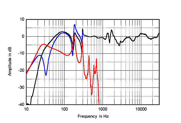
Although Alta describes the Alyssa's woofer tuning as using what they call XTL, for Extended Transmission Line, the impedance graph looks very similar to that of a conventional ported design. The saddle in the impedance magnitude trace at a low 32Hz suggests that this is the tuning frequency of the Alyssa's port. This was confirmed by the fact that the nearfield response of the woofer (fig.3, blue trace) has its minimum-motion notch at the same frequency, which is when the back pressure from the port resonance holds the cone stationary. This is extended low-frequency performance for a relatively small loudspeaker.
Fig.3 Alta Alyssa, anechoic response averaged across 30° horizontal window centered on the tweeter axis at 50", corrected for microphone response, with the nearfield responses of the woofer (blue), and port (red), and their complex sum (black), respectively plotted below 300Hz, 800Hz, and 300Hz.
However, the nearfield outputs of the woofer and port (red trace) are afflicted with severe resonant peaks, the two lowest in frequency coinciding with the frequencies of the discontinuities in the impedance traces. This behavior is most likely due to pipe resonances in the port and/or internal airspace and results in peaks and dips in the complex sum of the woofer and port outputs, taking into account acoustic phase and the different distance of each radiator from a nominal farfield microphone position (fig.3, black trace below 300Hz). I would expect this behavior to color the sound of male vocals.
No preferred listening axis is mentioned in the Alyssa's manual, so I performed the farfield measurements on an axis level with the center of the ribbon tweeter. The Alta's farfield response, averaged across a 30° horizontal window centered on the tweeter axis, is shown as the black trace above 300Hz in fig.3. The response trend is relatively even between 300Hz and 1100Hz, but there are two sharp resonant peaks in the octave immediately above that region, with then a slight lack of energy in what appears to be the crossover region. The response trend in the mid- and high treble is relatively even. This graph was taken without the grille; repeating it with the grille in place gave the same result above 5kHz, but with 2–3dB more energy in the crossover region and up to 5dB less energy in the presence region.
Fig.4 Alta Alyssa, lateral response family at 50", normalized to response on tweeter axis, from back to front: differences in response 90–5° off axis, reference response, differences in response 5–90° off axis.
Fig.5 Alta Alyssa, vertical response family at 50", normalized to response on tweeter axis, from back to front: differences in response 45–5° above axis, reference response, differences in response 5–45° below axis.
Fig.6 Alta Alyssa, step response on tweeter axis at 50" (5ms time window, 30kHz bandwidth).
Fig.7 Alta Alyssa, cumulative spectral-decay plot on tweeter axis at 50" (0.15ms risetime).
Though the Alta Alyssa's measured performance indicates that this relatively small speaker offers extended low frequencies and confirms that its ribbon tweeter is a high-quality driver, I remain concerned that the resonances in the upper bass and lower midrange regions and the others at the top of the woofer's passband will lead to audible coloration.—John Atkinson
Footnote 1: EPDR is the resistive load that gives rise to the same peak dissipation in an amplifier's output devices as the loudspeaker. See "Audio Power Amplifiers for Loudspeaker Loads," JAES, Vol.42 No.9, September 1994, and Keith Howard's article here.


