Sidebar 3: Measurements
I measured one of the Estelon Aura loudspeakers, serial number F35204B, in KR's apartment, using his NAD C 298 amplifier for the testing. I measured the Estelon Aura's impedance with Dayton Audio's DATS V2 system and used DRA Labs' MLSSA system with a calibrated DPA 4006 microphone to measure the speaker's behavior in the farfield and an Earthworks QTC-40 mike for the nearfield responses. Kal and I lifted the Aura on to a dolly for the measurements, but to minimize the effect of the first reflection from the ground, I measured the response and dispersion with the microphone at 1m rather than my usual 50".


Footnote 1: EPDR is the resistive load that gives rise to the same peak dissipation in an amplifier's output devices as the loudspeaker. See "Audio Power Amplifiers for Loudspeaker Loads," JAES, Vol.42 No.9, September 1994, and stereophile.com/reference/707heavy/index.html.
Fig.1 Estelon Aura, electrical impedance (solid) and phase (dashed) (2 ohms/vertical div.).
The Estelon Aura's sensitivity is specified as 90dB/2.83V, presumably measured at 1m. My B-weighted estimate was slightly lower, at 86.8dB(B)/2.83V/m. Estelon specifies the Aura's nominal impedance as 4 ohms, with a minimum value of 2 ohms at 58Hz. The speaker's impedance magnitude (fig.1, solid trace) varies considerably but lies above 4 ohms for almost the entire audioband, dropping below 4 ohms only in the bass. The minimum value was 1.9 ohms at 60Hz. The electrical phase angle (fig.1, dotted trace) affects the equivalent peak dissipation resistance, or EPDR (footnote 1). This lies below 3 ohms through most of the bass and midrange and below 2 ohms between 10Hz and 36Hz and between 57Hz and 92Hz. It drops below 1 ohm between 61Hz and 71Hz, with a minimum EPDR of 0.85 ohms at 65Hz. The Aura is a very demanding load for the partnering amplifier.
Fig.2 Estelon Aura, cumulative spectral-decay plot calculated from output of accelerometer fastened to the center of the side panel level with the lower midrange unit (measurement bandwidth, 2kHz).
When I listened to the enclosure with a stethoscope, I could hear a faint resonance in the upper midrange on the sidewalls. Using a plastic-tape accelerometer, I found two high-Q modes on the speaker's sides, at 406Hz and 1100Hz, as well as some low-Q activity at frequencies between these two modes (fig.2). However, the relatively high Q and the high frequencies will work against this behavior having audible consequences.
Fig.3 Estelon Aura, anechoic response on tweeter axis at 1m, averaged across 30° horizontal window and corrected for microphone response, with the nearfield midrange (blue) and woofer (red) responses and their complex sum respectively plotted below 300Hz, 500Hz, and 300Hz.
I was initially puzzled by the shape of the Estelon's impedance magnitude trace in the bass. The saddle centered on 60Hz lying between two small peaks suggests some sort of reflex alignment. However, KR clarified for me that the Aura's woofer is loaded with a sealed enclosure and crosses over to the two midrange units at a low 77Hz. The impedance peak at 105Hz will therefore be due to the crossover. The woofer's nearfield response (fig.3, red trace) peaks sharply between 50Hz and 70Hz and rolls off below that region with the ultimate 12dB/octave slope typical of a sealed-box alignment. The unit's upper-frequency rolloff is steep, and while the output above 125Hz is disturbed by some hash, this is low in level and any audible consequences will be reduced by the fact that the woofer fires down toward the floor.
The two midrange units behaved identically. Their summed nearfield response (fig.3, blue trace) rolls off below 100Hz with a sealed-box 12dB/octave slope and crosses over to the woofer close to the specified 77Hz. The black trace below 300Hz in fig.3 shows the complex sum of the midrange and woofer outputs. The small peak in the upper bass will be due to the nearfield measurement technique, which assumes that the drive units are placed on a true infinite baffle, ie, one which extends to infinity in both vertical and horizontal planes. However, the woofer's output does appear to be underdamped.
Fig.4 Estelon Aura, lateral response family at 1m, normalized to response on tweeter axis, from back to front: differences in response 45–5° off axis, reference response, differences in response 5–45° off axis.
Fig.5 Estelon Aura, vertical response family at 1m, normalized to response on tweeter axis, from back to front: differences in response 15–5° above axis, reference response, differences in response 5–10° below axis.
The black trace above 300Hz in fig.3 shows the Estelon's farfield output averaged across a 30° horizontal window centered on the tweeter axis. Other than some small peaks at the top of the midrange and between 7kHz and 10kHz and a slight lack of top-octave energy, the balance is relatively even. The Aura's horizontal dispersion, plotted 45° to each side of the tweeter axis (fig.4), is superbly well-controlled up to 17kHz, with the tweeter's output rolling off to the speaker's sides above that frequency. In the vertical plane (fig.5), the balance is maintained 5° below the tweeter axis, which is useful considering that the tweeter is a high 40" from the floor.
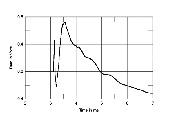
Fig.6 Estelon Aura, step response on tweeter axis at 1m (5ms time window, 30kHz bandwidth).
Turning to the time domain, the Aura's step response on the tweeter axis (fig.6) indicates that the tweeter and midrange units are all connected in positive acoustic polarity. The tweeter's output arrives first at the microphone, and the decay of its step smoothly blends with the start of the midrange units' step, which implies an optimal crossover implementation.
Fig.7 Estelon Aura, cumulative spectral-decay plot on tweeter axis at 1m (0.15ms risetime).
Because of its narrow low-frequency passband, the woofer's step is not visible in this graph. However, a nearfield step-response measurement (not shown) indicated that the driver is connected in inverted acoustic polarity, the step overlaid with ringing at the unit's tuning frequency. At higher frequencies, while the Estelon's cumulative spectral-decay (waterfall) plot (fig.7) features a clean initial decay across the audioband, some low-level delayed energy is present at the frequencies of the small peaks in the farfield response. (As always, ignore the apparent low-level ridge of delayed energy just below 16kHz, which is due to interference from the MLSSA host PC's video circuitry.)
In most respects, the Estelon Aura measured well, with a generally even frequency response, superbly controlled horizontal dispersion, time-coherent output, an initially clean waterfall plot, and a well-behaved enclosure. However, that very demanding impedance coupled with average sensitivity means that amplifier matching will be critical in getting the best from this loudspeaker, as Kal found in his audition.—John Atkinson
Footnote 1: EPDR is the resistive load that gives rise to the same peak dissipation in an amplifier's output devices as the loudspeaker. See "Audio Power Amplifiers for Loudspeaker Loads," JAES, Vol.42 No.9, September 1994, and stereophile.com/reference/707heavy/index.html.