Sidebar 3: Measurements
I measured the Grandinote Shinai using my Audio Precision SYS2722 analyzer (see the January 2008 "As We See It." Before doing any testing I preconditioned the amplifier by following the CEA's recommendation of operating it at one-eighth the specified power into 8 ohms for 30 minutes. At the end of that time, while the black-finished chassis was warm, at 89°F (31.7°C), the chrome grille on the top panel that covers the internal heatsinks was very hot, at 125.8°F (52.1°C). I then performed the older FTC/IHF thermal stress test by running the amplifier at one-third the specified power into 8 ohms for an hour. At the end of that time, the chrome grille's temperature was a little cooler at 123.3°F (50.8°C). As the Shinai biases its output devices into class-A, it actually runs hottest with no signal and coolest at high powers. The amplifier has sufficient heatsinking capacity, but users should make sure it has plenty of ventilation.
The voltage gain at 1kHz into 8 ohms with the volume control set to its maximum setting ("33") was 31.6dB from the single-ended inputs and 6dB lower from the balanced inputs. The amplifier preserved absolute polarity (ie, was noninverting) with both input types. The volume control operated in accurate 1dB steps, and the Mute button applied a full mute. The single-ended input impedance was a usefully high 42.5k ohms at low and middle frequencies, dropping to 29.1k ohms at the top of the audioband. The balanced input impedance was twice these values at 20Hz and 1kHz but 68.8k ohms at 20kHz.
The Grandinote's output impedance, including the series impedance of 6' of loudspeaker cable, was relatively high for a solid-state design, at 0.24 ohm at 20Hz and 1kHz, increasing very slightly to 0.265 ohm at 20kHz. The modulation of the amplifier's frequency response, due to the Ohm's law interaction between this source impedance and the impedance of our standard simulated loudspeaker, reached ±0.25dB (fig.1, gray trace). The response into pure resistive loads, taken with the volume control set to its maximum, was flat to 20kHz and rolled off above the audioband, reaching –0.8dB at 200kHz into 8 ohms (fig.1, blue and red traces), –0.75dB at 100kHz into 4 ohms (cyan, magenta), and –2dB at 100kHz into 2 ohms (green). Note the excellent channel matching and that, commendably, the response didn't change appreciably at lower settings of the volume control. These responses were taken with the balanced inputs; the unbalanced inputs were also flat to 20kHz but started rolling off a little earlier at ultrasonic frequencies (fig.2). At the other end of the spectrum, the single-ended inputs' response was down by 1.4dB at 10Hz. The extended ultrasonic response was responsible for the amplifier's excellent reproduction of a 10kHz squarewave (fig.3).


 The Grandinote Shinai's measured performance is dominated by the designer's decision not to use negative feedback. I would expect the Shinai's sonic character therefore to be similar to that of a typical tube amplifier. I don't recommend using this amplifier with loudspeakers whose impedance drops much below 4 ohms.—John Atkinson
Footnote 1: In an interview, designer Massimiliano Magri told Rob Schryer that the maximum output power is the same—37W—into 8 or 4 ohms.—Editor
Fig.1 Grandinote Shinai, balanced inputs. frequency response at 2.83V into: simulated loudspeaker load (gray), 8 ohms (left channel blue, right red), 4 ohms (left cyan, right magenta), 2 ohms (green) (0.5dB/vertical div.).
Fig.2 Grandinote Shinai, single-ended inputs, frequency response at 2.83V into 8 ohms (left channel gray, right green) (0.5dB/vertical div.).
Fig.3 Grandinote Shinai, small-signal, 10kHz squarewave into 8 ohms.
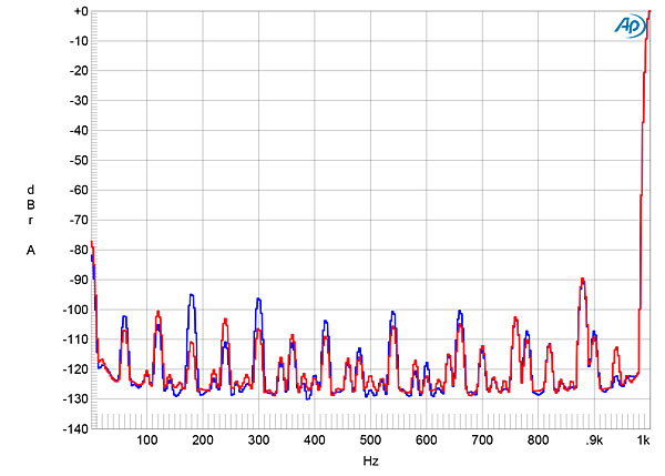
As expected from the dual-mono construction, channel separation was excellent: >100dB in both directions below 3kHz. Measured with the unbalanced inputs shorted to ground and the volume control set to its maximum, the wideband, unweighted signal/noise ratio (ref. 2.83V into 8 ohms) measured a very good 79.4dB (average of both channels). Restricting the measurement bandwidth to 22kHz increased the ratios to 86.6dB, left, and 83.1dB, right, and an A-weighting filter increased them further, to 93.0dB, left, and 87.8dB, right. Spectral analysis of the Grandinote amplifier's low-frequency noise floor (fig.4) revealed that spuriae related to the AC power-line frequency were low in level; the 180Hz component was a little higher in the left channel (blue trace) than the right (red). The component at 880Hz (1000–120Hz) was the highest in level in both channels, at –90dB ref. 2.83V (0.003%).
Fig.4 Grandinote Shinai, spectrum of 1kHz sinewave, DC–1kHz, at 1W into 8 ohms (left channel blue, right red; linear frequency scale).
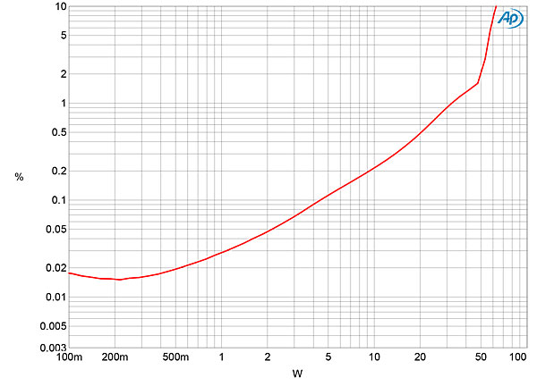
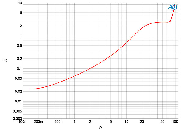
The Grandinote Shinai is specified as delivering 37Wpc, with no load impedance or distortion level mentioned (footnote 1). At our usual definition of clipping, which is when the THD+noise reaches 1%, with both channels driven the Grandinote delivered 30Wpc into 8 ohms (fig.5, 14.8dBW) and 36Wpc into 4 ohms (fig.6, 12.55dBW). Relaxing the criteria to 3% THD+N, the Shinai clipped at 34Wpc into 8 ohms (15.3dBW) and at 54Wpc into 4 ohms (14.3dBW). Into 2 ohms (fig.7), even with just one channel driven, it reached 1% THD+N at 15W (5.75dBW), and though actual waveform clipping was relatively mild below 70W into 2 ohms, the THD+N remained between 2% and 3% between 20W and 70W.
Fig.5 Grandinote Shinai, distortion (%) vs 1kHz continuous output power into 8 ohms.
Fig.6 Grandinote Shinai, distortion (%) vs 1kHz continuous output power into 4 ohms.
Fig.7 Grandinote Shinai, distortion (%) vs 1kHz continuous output power into 2 ohms.
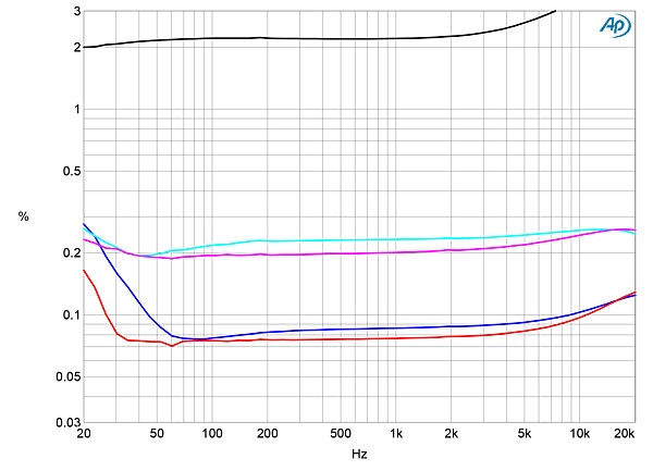
I measured how the THD+N percentage changed with frequency at 6.33V, which is equivalent to 5W into 8 ohms, 10W into 4 ohms, and 20W into 2 ohms. Other than in the low bass, the distortion levels were consistent with frequency (fig.8) but increased significantly as the load impedance halved. The gray trace in this graph shows the behavior into 2 ohms; I would not recommend using this amplifier into such a demanding load.
Fig.8 Grandinote Shinai, THD+N (%) vs frequency at 6.33V into: 8 ohms (left channel blue, right red), 4 ohms (left cyan, right magenta), and 2 ohms (gray).
The shape of the THD+N spuriae waveform at moderate power into 8 ohms (fig.9, bottom trace) suggests that the distortion signature predominantly consists of the subjectively innocuous second and third harmonics. This was confirmed by spectral analysis (fig.10), though higher-order harmonics can be seen at or below –80dB (0.01%). At the same power into 4 ohms (fig.11), the third harmonic dominates, though the higher-order harmonics don't get any higher in level. With its bent transfer function, the Shinai did only okay with an equal mix of 19kHz and 20kHz tones, the combined waveform peaking at 10W into 8 ohms (fig.12). The second-order difference product lay at –70dB (0.03%) with higher-order intermodulation products a little higher in level.
Fig.9 Grandinote Shinai, 1kHz waveform at 10W into 8 ohms, 0.14% THD+N (top); distortion and noise waveform with fundamental notched out (bottom, not to scale).
Fig.10 Grandinote Shinai, spectrum of 50Hz sinewave, DC–1kHz, at 10Wpc into 8 ohms (left channel blue, right red; linear frequency scale).
Fig.11 Grandinote Shinai, spectrum of 50Hz sinewave, DC–1kHz, at 10Wpc into 4 ohms (left channel blue, right red; linear frequency scale).
Fig.12 Grandinote Shinai, HF intermodulation spectrum, DC–30kHz, 19+20kHz at 10Wpc peak into 8 ohms (left channel blue, right red; linear frequency scale).
Footnote 1: In an interview, designer Massimiliano Magri told Rob Schryer that the maximum output power is the same—37W—into 8 or 4 ohms.—Editor


