Sidebar 3: Measurements
I used DRA Labs' MLSSA system, an Earthworks microphone preamplifier, and a calibrated DPA 4006 microphone to measure the MayFly MF-201's farfield behavior, and an Earthworks QTC-40 mike for its nearfield responses. I used an Outline computer-controlled turntable to examine the off-axis behavior, rotating the loudspeaker under test in 5° increments.
Though MayFly specifies the MF-201's sensitivity as 88dB/W/m, my estimate was significantly lower, at 83dB(B)/2.83V/m. While the MF-201's impedance is specified as 8 ohms, the impedance magnitude (fig.1, solid trace) measured with Dayton Audio's DATS V2 system remains above 10 ohms for almost all the audioband, which means that the 2.83V at which I estimate sensitivity will be slightly less than 1W.
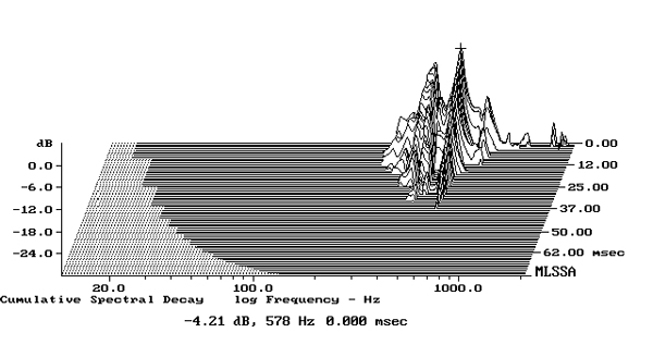
 There is a discontinuity between 300Hz and 400Hz in the impedance and phase traces in fig.1, which implies that there is a resonance of some kind in that region. I investigated the enclosure's vibrational behavior with a plastic-tape accelerometer; while I found resonant modes on all the surfaces, there were none in that region. The highest-level mode was at 578Hz on the top panel and the front baffle (fig.2). However, this top-panel resonance has a fairly high Q (Quality Factor) and is relatively high in frequency, all of which will work against audibility. (A high-Q resonance needs to be hit with sustained tones lasting for a relatively long time before it is fully excited, and the higher its frequency the greater the chance that it lies between the frequencies of the notes in the well-tempered musical scale, footnote 2.)
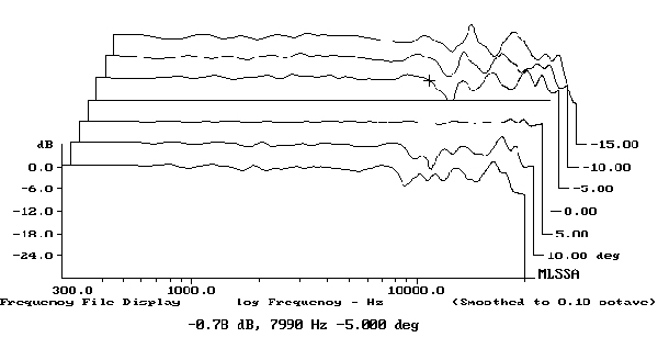
 The MayFly's horizontal dispersion is shown in fig.4. (The traces are normalized to the response on the tweeter axis, which thus appears as a straight line.) The radiation pattern is well controlled throughout the midrange and low treble, but the off-axis behavior is complex in the region where the on-axis response has narrow peaks and dips. Experimentation with toe-in may well optimize the treble balance. Due to its circular cabinet cross-section, it wasn't possible to place the MF-201 on its side on the Outline turntable's stand to examine the loudspeaker's vertical dispersion. However, the vertical radiation pattern over a ±15° range, again normalized to the response on the tweeter axis, is shown in fig.5. As expected from the symmetrical drive-unit array, it is similar to the speaker's behavior in the horizontal plane.

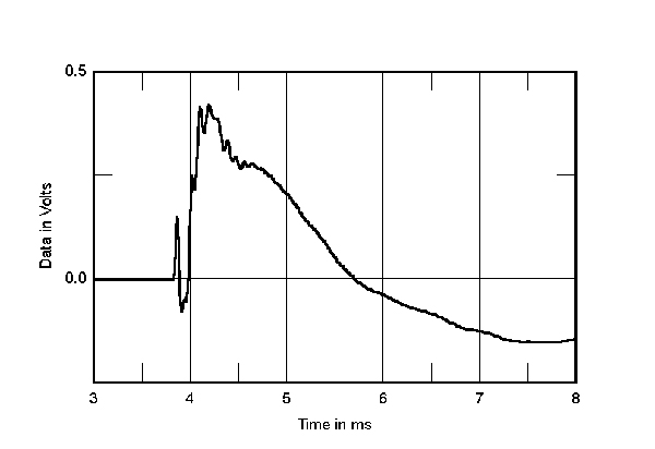
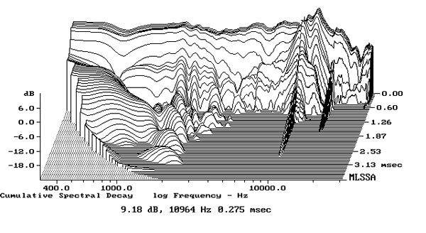
 In the time domain, the MF-201's step response on the tweeter axis (fig.6) indicates that, as expected from its being mounted at the front of the woofer's pole-piece, the tweeter's output arrives first at the microphone. Both drive units are connected in positive acoustic polarity. The decay of the tweeter's step doesn't quite blend smoothly with the start of the woofer's step, and some reflections of the tweeter's output can be seen overlaying the woofer's output. The MF-201's cumulative spectral-decay plot (fig.7) is clean in the midrange and mid-treble, though some ridges of resonant decay can be seen above 10kHz.
Footnote 1: EPDR is the resistive load that gives rise to the same peak dissipation in an amplifier's output devices as the loudspeaker. See "Audio Power Amplifiers for Loudspeaker Loads," JAES, Vol.42 No.9, September 1994, and stereophile.com/reference/707heavy/index.html.
Footnote 2: See my article on loudspeaker panel resonances here.
Fig.1 MayFly MF-201, electrical impedance (solid) and phase (dashed) (2 ohms/vertical div.).
The minimum impedance is 6.8 ohms between 185Hz and 200Hz and 6.1 ohms at 8.6kHz and the electrical phase angle (dashed trace) is occasionally high, which will increase the loudspeaker's demand for current from an amplifier. Consequently, the EPDR (footnote 1) drops below 4 ohms between 92Hz and 148Hz and between 3.25kHz and 9.7kHz, with minimum values of 3.46 ohms at 114Hz and 2.37 ohms at 5.3kHz. With its relatively low sensitivity and despite its often-high impedance, the MF-201 will work best with amplifiers that have no problems driving 4 ohm loads.
Fig.2 MayFly MF-201, cumulative spectral-decay plot calculated from output of accelerometer fastened to center of front baffle below coaxial drive-unit (MLS driving voltage to speaker, 7.55V; measurement bandwidth, 2kHz).
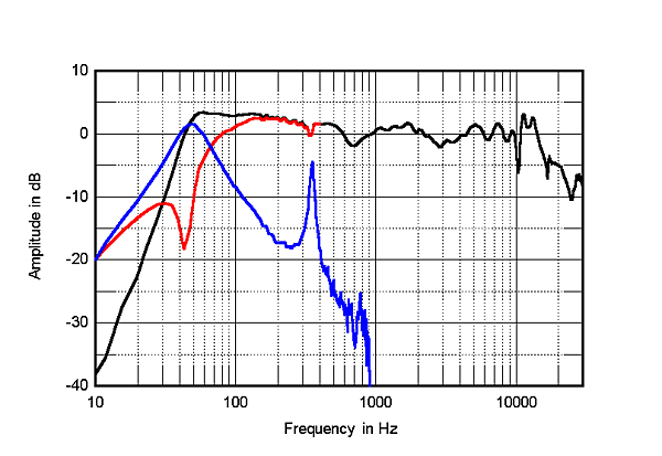
The saddle centered on 43Hz in the impedance magnitude trace suggests that this is the tuning frequency of the port at the base of the baffle. The blue trace in fig.3 shows the port's nearfield response. Its output broadly peaks slightly higher in frequency than the port tuning frequency, and while the upper-frequency rolloff is clean, a high-level peak is present at 352Hz. This correlates with the discontinuity at the same frequency in the impedance traces. The red trace below 400Hz shows the response of the woofer, again measured in the nearfield. It has the expected minimum-motion notch at the port tuning frequency, which is when the back pressure from the port resonance holds the cone still. However, there is also a notch at the frequency of the midrange peak in the port's output. A frequency of 352Hz has a half-wavelength of 487mm, which is similar to the internal height of the MF-201's enclosure. It is possible, therefore, that the peak at this frequency is due to an internal standing wave corresponding to the loudspeaker's height.
Fig.3 MayFly MF-201, anechoic response on tweeter axis at 50", averaged across 30° horizontal window and corrected for microphone response, with the nearfield response of the port (blue), woofer (red), and the complex sum of their nearfield responses respectively plotted below 900Hz, 400Hz, and 400Hz.
The black trace below 400Hz in fig.3 shows the complex sum (amplitude and phase) of the nearfield woofer and port outputs. The usual boost in the upper bass due to the nearfield measurement technique, which assumes that the drive units are mounted on a true infinite baffle—ie, a plane that extends to infinity in both dimensions—is absent. This suggests that the MayFly's woofer alignment is overdamped, favoring articulation over bass weight. As a result, the MF-201 will benefit from the low-frequency boundary reinforcement that results from a placement close to the wall behind the speaker.
The black trace above 400Hz in fig.3 shows the MF-201's farfield response averaged across a 30° horizontal window centered on the tweeter axis. The speaker's balance is generally even, though with a slight lack of energy in the upper midrange and the presence region. The narrow peaks and dips in the response in the top two octaves will be due to reflections of the coaxially mounted tweeter's output from the woofer surround.
Fig.4 MayFly MF-201, lateral response family at 50", normalized to response on tweeter axis, from back to front: differences in response 90–5° off axis, reference response, differences in response 5–90° off axis.
Fig.5 MayFly MF-201, vertical response family at 50", normalized to response on tweeter axis, from back to front: differences in response 15–5° above axis, reference response, differences in response 5–15° below axis.
Fig.6 MayFly MF-201, step response on tweeter axis at 50" (5ms time window, 30kHz bandwidth).
Fig.7 MayFly MF-201, cumulative spectral-decay plot on tweeter axis at 50" (0.15ms risetime).
The MayFly MF-201's use of a coaxially mounted tweeter affects its measured performance in a predictable manner. But with care taken in placement and toe-in, the result should be a generally even perceived tonal balance.—John Atkinson
Footnote 1: EPDR is the resistive load that gives rise to the same peak dissipation in an amplifier's output devices as the loudspeaker. See "Audio Power Amplifiers for Loudspeaker Loads," JAES, Vol.42 No.9, September 1994, and stereophile.com/reference/707heavy/index.html.


