Sidebar 3: Measurements
Prior to measuring the Pass Labs INT-25 using my Audio Precision SYS2722 system, I preconditioned it for an hour at one-third power into 8 ohms. At the end of that time, the heatsinks on the amplifier's sides were hot, at 122°F (50°C), as was the top panel, at 116.6°F (47.8°C). Owners should make sure this amplifier is well-ventilated. The amplifier's maximum voltage gain into 8 ohms was 25.4dB, and the amplifier preserved absolute polarity (ie, was noninverting).
The Pass Labs' input impedance is specified as 47k ohms; I measured 46k ohms at 20Hz and 1kHz and 37k ohms at 20kHz. The small reduction at the top of the audioband will be inconsequential. The output impedance was very low, at 0.06 ohms at low and middle frequencies, rising very slightly to 0.08 ohms at the top of the audioband. (Both measured impedances include the series resistance of 6' of speaker cable.) Consequently, the variation in frequency response with our standard simulated loudspeaker (fig.1, gray trace) was minimal. The response into impedances of 4 and 8 ohms (fig.1, cyan, magenta, blue, and red traces) was flat up to 20kHz, and the output into 2 ohms (green trace) was down by just 0.25dB at 20kHz. The ultrasonic rolloff varied with the load impedance; the –3dB point was close to 200kHz into higher impedances but dropped to 100kHz into 2 ohms. The traces in fig.1 were taken with the volume control set to its maximum. Commendably, the frequency response didn't change at lower settings of the volume control, and the already good channel matching improved. The Pass Labs' reproduction of a 10kHz squarewave into 8 ohms (fig.2) featured very short risetimes and no ringing, though there was a very slight hint of overshoot.

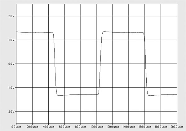

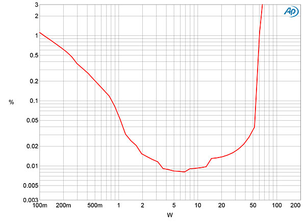
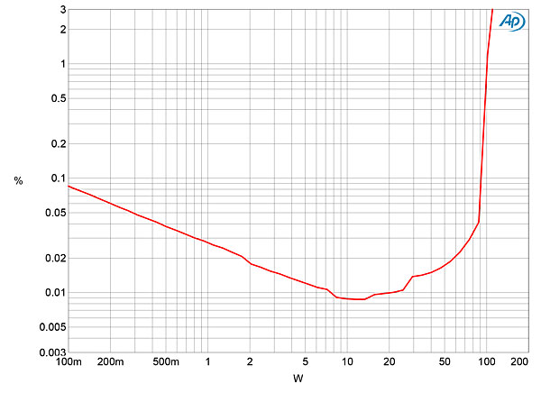

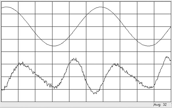

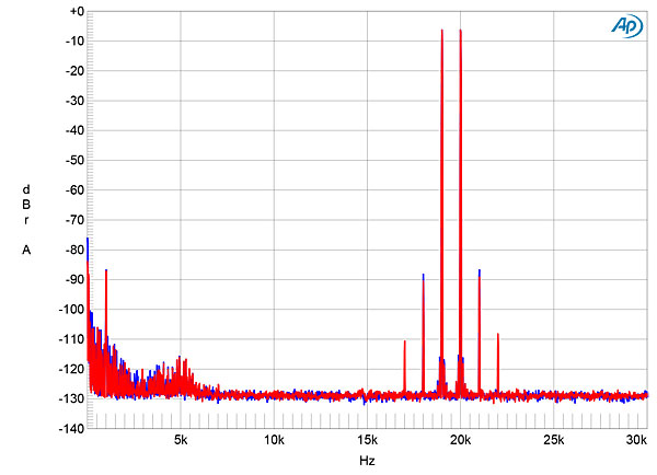
Fig.1 Pass Labs INT-25, frequency response at 2.83V into: 8 ohms (left channel blue, right channel red), 4 ohms (left cyan, right magenta), 2 ohms (gray) (0.5dB/vertical div.).
Fig.2 Pass Labs INT-25, small-signal, 10kHz squarewave into 8 ohms.
Channel separation was very good, but asymmetrical at >77dB, R–L, and >90dB, L–R, below 1kHz. Both figures dropped to close to 60dB at the top of the audioband, however. The wide-band, unweighted S/N ratio, ref. 2.83V and measured with the volume control set to its maximum and the input shorted to ground, was 75.1dB (average of both channels), which improved to 83.2dB when the measurement bandwidth was restricted to the audioband, and to 86.9dB when A-weighted. Spectral analysis of the INT-25's noise floor (fig.3) revealed a low level of random noise, but spuriae related to the power-line frequency were present at low levels. The 60Hz component, which will be due to magnetic interference from the power transformer, was highest in level, at –76dB.
Fig.3 Pass Labs INT-25, spectrum of 1kHz sinewave, DC–1kHz, at 1W into 8 ohms (linear frequency scale).
The INT-25's output power is specified as 25W into 8 ohms and 50W into 4 ohms, both equivalent to 14dBW, with a "class-A envelope" of 50W peak into 2, 4, or 8 ohm loads. With "clipping" defined as when the THD+noise reaches 1%, I found that the Pass Labs amplifier with both channels driven at 1kHz clipped at 60W into 8 ohms (17.8dBW, fig.4) and 98W into 4 ohms (16.9dBW, fig.5). Fig.6 shows how the INT-25's THD+N percentage varied with frequency at a moderate output voltage of 8.95V, which is equivalent to 10W into 8 ohms, 20W into 4 ohms, and 40W into 2 ohms. While the Pass Labs offered very low distortion at all frequencies into 8 ohms (blue and red traces), with only a small increase at the top of the audioband, the distortion at this output level increased dramatically above the midrange into 4 ohms (cyan and magenta traces) and 2 ohms (gray trace). It is possible that this behavior is associated with the amplifier's output stage moving out of the class-A bias condition.
Fig.4 Pass Labs INT-25, distortion (%) vs 1kHz continuous output power into 8 ohms.
Fig.5 Pass Labs INT-25, distortion (%) vs 1kHz continuous output power into 4 ohms.
Fig.6 Pass Labs INT-25, THD+N (%) vs frequency at 8.95V into: 8 ohms (left channel blue, right channel red), 4 ohms (left cyan, right magenta), and 2 ohms (gray).
The waveform of the residual distortion and noise with a 1kHz signal at this voltage into 8 ohms (fig.7) is dominated by the subjectively benign second harmonic. This was confirmed by spectral analysis (fig.8), though it is appropriate to note that the second harmonic lies at a very low –86dB (0.005%). Higher-order harmonics are virtually absent, though the low-level power supply–related spuriae can be seen in this graph. Both high-order intermodulation products and the second-order difference product with the INT-25 driving an equal mix of 19kHz and 20kHz tones at a peak level of 10W into 8 ohms were very low in level (fig.9). However, as expected from fig.6, repeating this test at the same output voltage into 4 ohms produced high levels of intermodulation distortion. I had to reduce the peak output level to 6.32V into 4 ohms, equivalent to 10W into this load, to get a similar spectrum to that shown in fig.9.
Fig.7 Pass Labs INT-25, 1kHz waveform at 10W into 8 ohms, 0.0092% THD+N (top); distortion and noise waveform with fundamental notched out (bottom, not to scale).
Fig.8 Pass Labs INT-25, spectrum of 50Hz sinewave, DC–1kHz, at 10W into 8 ohms (linear frequency scale).
Fig.9 Pass Labs INT-25, HF intermodulation spectrum, DC–30kHz, 19+20kHz at 10W peak into 8 ohms (linear frequency scale).
There is much to admire in the Pass Labs INT-25's measured performance. However, its intolerance in the treble for loads of 4 ohms and below means it will work best with loudspeakers whose impedance doesn't drop below 8 ohms at high frequencies.—John Atkinson


