Sidebar 3: Measurements
I measured the Schiit Audio Yggdrasil with my Audio Precision SYS2722 system (see the January 2008 "As We See It"). As well as the Audio Precision's digital outputs, I used WAV and AIFF test-tone files sourced via USB from my MacBook Pro running on battery power with Pure Music 3.0. Apple's USB Prober utility identified the Schiit DAC as "Schiit Audio Gen 3 USB" from "Schiit," and identified the USB interface device as being from "C-MEDIA ELECTRONICS INC." The USB port operated in the optimal isochronous asynchronous mode. Apple's AudioMIDI utility revealed that, via USB, the Yggdrasil accepted 16-, 24-, and 32-bit integer data sampled at all rates from 44.1 to 192kHz.
The Schiit's maximum output was very slightly higher than the specification, at 4.24V balanced and 2.06V unbalanced; and both sets of outputs preserved absolute polarity, meaning that the XLR jacks are wired with pin 2 hot. The output impedance was a low 196 ohms across the audioband from the balanced outputs, and 180 ohms from the unbalanced outputs, though the latter rose slightly, to 202 ohms, at the bottom of the audioband.
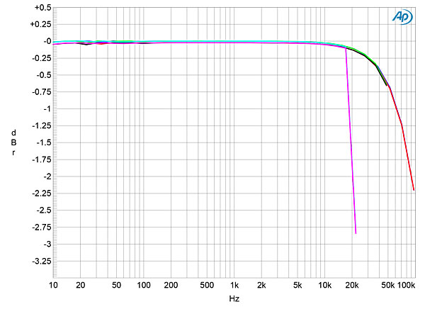
The Yggdrasil's impulse response with data sampled at 44.1kHz is shown in fig.1. Taken from the left channel's output, it reveals the Yggdrasil's reconstruction filter to be a time-symmetrical, finite-impulse-response type, but with more coefficients than is usually seen with this type of filter. This filter produces a very sharp rolloff above the audioband, as evidenced by the red and magenta traces in fig.2 (footnote 1). The blue and cyan traces in fig.2 show the spectrum of the Schiit's output while being fed 24-bit data representing a full-scale 19.1kHz tone. While the image of the tone at 25kHz is suppressed by almost 90dB and harmonic distortion is very low, the noise floor looks much more ragged than I usually see (footnote 2).


 With undithered data and a signal at exactly –90.31dBFS, the Yggdrasil output a superbly symmetrical waveform, with the three DC voltage levels described by the data very well defined and the ringing due to the reconstruction filter clearly visible (fig.6). With undithered 24-bit data at the same level (fig.7), although the overall shape of the reconstructed sinewave is good, you can see significant errors at the signal's zero-crossing points. Again, this will be due to the design choice to use 20-bit converters.

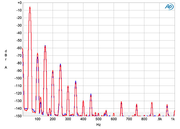
 Distortion levels with high-impedance loads were low, as can be seen in fig.8, where the second and third harmonics lie between –90 and –100dBFS (0.001 and 0.003%) in both channels. However, the Schiit clipped with signals higher than –10dBFS into the punishing 600-ohm load (fig.9). I then tested the Yggdrasil for intermodulation distortion with an equal mix of 19 and 20kHz tones (fig.10), and while the actual intermodulation products were between 90 and 100dB below the signal's peak level, the noise floor again looked ragged, as in fig.2. I suspect that the digital filter begins to overload with full-scale high-frequency tones. As music only very rarely contains such spectral content, perhaps the filter and DSP circuits have been optimized for low-level signals.


Footnote 1: My thanks to Jürgen Reis of MBL for suggesting this test to me. Footnote 2: See, for example, figs. 4 and 5 here.
Fig.1 Schiit Yggdrasil, impulse response (one sample at 0dBFS, 44.1kHz sampling, 4ms time window).
Fig.2 Schiit Yggdrasil, wideband spectrum of white noise at –4dBFS (left channel red, right magenta) and 19.1kHz tone at 0dBFS (left blue, right cyan), with data sampled at 44.1kHz (20dB/vertical div.).
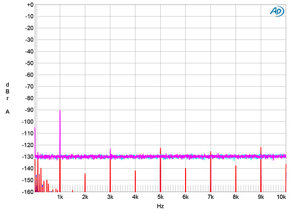
Fig.3 shows the frequency response at a lower level, –12dBFS, with sample rates of 44.1, 96, and 192kHz. Other than the expected sharp cutoff at half of the two lower sample rates, the responses follow the same basic shape, with a smooth rolloff above the audioband. Note the excellent channel matching in this graph. The Yggdrasil also offered superb channel separation, especially from its balanced output jacks, where the crosstalk in both directions was below –125dB below 2kHz, and still below –110dB at 20kHz. Channel separation from the unbalanced outputs was 6dB or so lower at high frequencies, but the crosstalk was 20dB worse at low frequencies. The Yggdrasil also offered superbly low levels of analog self-noise. Fig.4 shows spectral analysis of the DAC's low-frequency noise floor while it reproduced a full-scale 1kHz tone. The random noise components lie at the level of my analyzer, and the only supply components that can be seen are at 120Hz, at –135dB in the left channel and –130dB in the right. This indicates excellent analog circuit design and circuit-board layout.
Fig.3 Schiit Yggdrasil, frequency response at –12dBFS into 100k ohms with data sampled at: 44.1kHz (left channel cyan, right magenta), 96kHz (left green, right gray), 192kHz (left blue, right red) (0.5dB/vertical div.).
Fig.4 Schiit Yggdrasil, spectrum with noise and spuriae of dithered 24-bit, 1kHz tone at 0dBFS (left channel blue, right red; 20dB/vertical div.).
Because of the Schiit's low level of analog noise, I extended to 160dB the vertical scale for the spectral analysis of its output with a dithered 1kHz tone at –90dBFS (fig.5). The noise floor with 16-bit data (cyan and magenta traces) is actually the dither noise used to encode the data. However, with 24-bit data (blue, red), while the noise floor lies at or below –160dBFS, a regular series of distortion components can be seen, in which the third, fifth, seventh, or ninth harmonics are highest in level. This will be due to the Yggdrasil's use of 20-bit D/A converters; the bottom four bits with 24-bit data will be truncated.
Fig.5 Schiit Yggdrasil, spectrum with noise and spuriae of dithered 1kHz tone at –90dBFS with: 16-bit data (left channel cyan, right magenta), 24-bit data (left blue, right red) (20dB/vertical div.).
Fig.6 Schiit Yggdrasil, waveform of undithered 1kHz sinewave at –90.31dBFS, 16-bit data (left channel blue, right red).
Fig.7 Schiit Yggdrasil, waveform of undithered 1kHz sinewave at –90.31dBFS, 24-bit data (left channel blue, right red).
Fig.8 Schiit Yggdrasil, spectrum of 50Hz sinewave, DC–1kHz, at 0dBFS into 100k ohms (left channel blue, right red; linear frequency scale).
Fig.9 Schiit Yggdrasil, spectrum of 50Hz sinewave, DC–1kHz, at –10dBFS into 600 ohms (left channel blue, right red; linear frequency scale).
Fig.10 Schiit Yggdrasil, HF intermodulation spectrum, DC–30kHz, 19+20kHz at 0dBFS into 100k ohms, 44.1kHz data (left channel blue, right red; linear frequency scale).
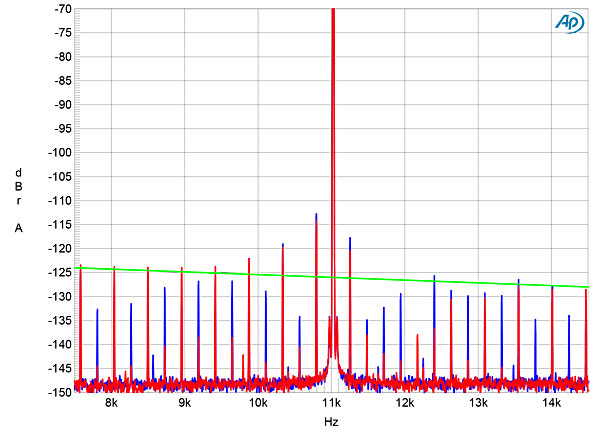
Tested for its rejection of word-clock jitter with a 16-bit J-Test signal, the Schiit Yggdrasil had some problems (fig.11). Although most of the odd-order harmonics of the LSB-level, low-frequency squarewave in the right channel (red trace) are close to the correct level (green line), many components are suppressed, particularly in the left channel (blue), and the two sidebands closest to the spectral spike that represents the 11.025kHz tone are boosted. This behavior was identical with coaxial and optical S/PDIF data and with USB data. With 24-bit data, there were still some very low-level sidebands visible in the left channel with a USB datastream (fig.12, blue trace), but not with S/PDIF data.
Fig.11 Schiit Yggdrasil, high-resolution jitter spectrum of analog output signal, 11.025kHz at –6dBFS, sampled at 44.1kHz with LSB toggled at 229Hz: 16-bit coaxial S/PDIF data (left channel blue, right red). Center frequency of trace, 11.025kHz; frequency range, ±3.5kHz.
Fig.12 Schiit Yggdrasil, high-resolution jitter spectrum of analog output signal, 11.025kHz at –6dBFS, sampled at 44.1kHz with LSB toggled at 229Hz: 24-bit USB data (left channel blue, right red). Center frequency of trace, 11.025kHz; frequency range, ±3.5kHz.
It's difficult to sum up the Schiit Yggdrasil's measured behavior. While the processor's analog circuitry is superbly well designed, its digital circuitry appears to have problems with high-level, high-frequency tones, and with the LSBs of 24-bit data. It's possible, of course, that the former will be rare with music, and that the latter will be obscured by the noise floors of recordings. But it does look as if the digital circuitry is not fully optimized. Hopefully, this could be addressed with a firmware upgrade.—John Atkinson
Footnote 1: My thanks to Jürgen Reis of MBL for suggesting this test to me. Footnote 2: See, for example, figs. 4 and 5 here.


