Sidebar 2: Measurements
Unlike the very high output levels of other Theta products, the Cobalt 307 DAC had a maximum output of 2.027V (left channel) and 2.059V (right). This is very close to the 2V CD standard. Output impedance was 50 ohms across the band. This low value suggests the 307 DAC should have no trouble driving a power amplifier through a passive level control.
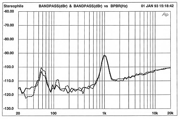
Frequency response and de-emphasis error are shown in fig.1. The right channel's 0.3dB higher output can be seen in the top trace. There is less HF rolloff than is usually measured in digital processors; the 307 DAC is down only a tenth of a dB at 20kHz. De-emphasis error (bottom traces) was virtually nonexistent, owing to the fact that it is performed in the digital domain by the Sony digital filter.
 Interchannel crosstalk (fig.2) was unusual in that channel separation decreased at low frequencies. Most crosstalk curves show the inverse of the 307 DAC's response, with crosstalk increasing with frequency. Note that left- and right-channel separation performance is virtually identical.


 The 307 DAC's reproduction of a full-scale, 1kHz squarewave is shown in fig.9. The clipped shape is typical of linear-phase digital filters such as the Sony CXD1244.


 Overall, the 307 DAC's bench performance was good for its price.—Robert Harley
Fig.1 Theta Cobalt 307, CD frequency response at –12dBFS into 100k ohms, with de-emphasis (bottom) and without (top). (Right channel dashed, 0.5dB/vertical div.)
Fig.2 Theta Cobalt 307, channel separation (10dB/vertical div.).
Looking at a 1/3-octave spectral analysis of the 307 DAC when decoding a –90dB, dithered 1kHz sinewave (fig.3), we can see a fairly high level of power-supply noise at 60Hz. This is, however, to be expected when the power transformers are located so close to the audio circuitry. Interestingly, there is some 120Hz in the right channel (dotted trace) not seen in the left channel. This noise is also seen in fig.4, a similar spectral analysis of the 307 DAC when driven by digital silence (all data words are zero). Note that fig.4 is plotted to 200kHz, and that there are no spikes that would indicate DAC idle tones or other artifacts.
Fig.3 Theta Cobalt 307, 1/3-octave spectrum of dithered 1kHz tone at –90dBFS, with noise and spuriae, 16-bit data (right channel dashed.)
Fig.4 Theta Cobalt 307, 1/3-octave spectrum of silent track, with noise and spuriae, 16-bit data (right channel dashed.)
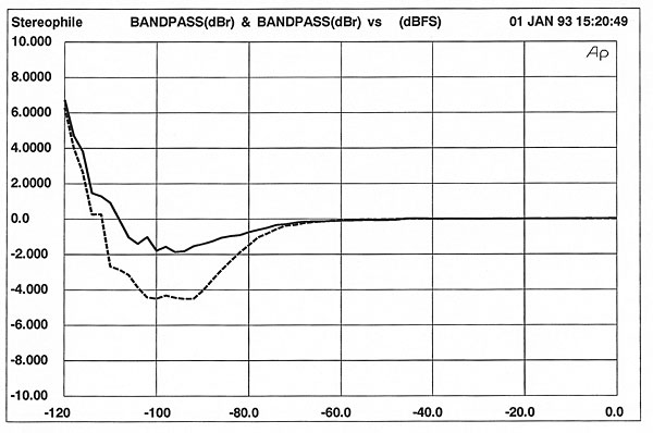
Low-level linearity (fig.5) was only fair, with a 4dB negative error at –90dB in the right channel. The low-bit operation of the PCM67 on low-level signals would be expected to produce less linearity error than is seen here.
Fig.5 Theta Cobalt 307, departure from linearity (right channel dashed, 2dB/vertical div.)
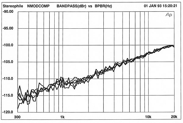
The 307 DAC's noise modulation performance was excellent, as seen in fig.6. The traces are very closely grouped, particularly above 2kHz. This indicates that the noise floor's spectral balance will shift very little as a function of input level. This was good performance, considering the mediocre linearity measurement; the two are closely related.
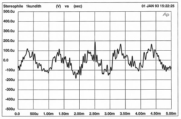
Fig.6 Theta Cobalt 307, waveform of undithered 1kHz sinewave at -90.31dBFS, 16-bit data.
The waveform produced by the 307 DAC when decoding a –90dB, undithered 1kHz sinewave is shown in fig.7. There is a fairly high level of audioband noise on the signal, and the waveform looks rather raggedy.
Fig.7 Theta Cobalt 307, noise modulation, –60 to –100dBFS (5dB/vertical div.)
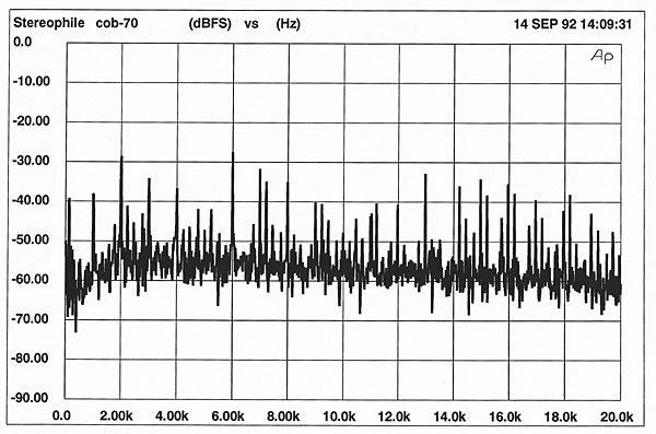
Fig.8 is an FFT-derived spectral analysis of the 307 DAC's output when driven by a full-scale mix of 19kHz and 20kHz. There is a remarkable absence of a 1kHz difference component, but there are several higher-order intermodulation components at 2kHz, 7kHz, 9kHz, 15kHz, 16kHz, and 17kHz. There is also an unusual rise in the noise floor centered on the test-signal frequencies. To explore this behavior, I repeated the analysis using different test-signal frequencies (not shown). As with the 19kHz and 20kHz analysis, there was a noise-floor rise at the frequency of the test signal. This rise was, however, greater at high frequencies, but maintained approximately the same bandwidth.
Fig.8 Theta Cobalt 307, HF intermodulation spectrum, DC–30kHz, 19+20kHz at 0dBFS into 100k ohms (linear frequency scale).
Fig.9 Theta Cobalt 307, 1kHz squarewave at 0dBFS.
As would be expected from Theta, the 307 DAC's jitter performance was good considering the unit's low price. The jitter level varied from 118ps (with no input signal) to 364ps (worst case, –90dB, 1kHz sinewave input). The jitter was less than 300ps with signal levels above –30dB. The Cobalt's jitter spectrum is shown in fig.10 (driven by a full-scale, 1kHz sinewave) and fig.11 (driven by a –70dB, 1kHz sinewave). Note the spikes at 1kHz and multiples of 1kHz, indicating the jitter is periodic and correlated to the input signal. Also note how the number of discrete-frequency jitter components rises with the lower input level. All jitter measurements were made at the 8fs (352.8kHz) clock pin on the PCM67 chip.
Fig.10 Theta Cobalt 307, jitter spectrum, 1kHz sinewave at 0dBFS.
Fig.11 Theta Cobalt 307, jitter spectrum, 1kHz sinewave at –70dBFS.
The 307 DAC had no problem locking to 32kHz and 48kHz sampling frequencies, and I measured less than 100µV of DC offset at the outputs, a very low level. Finally, the unit doesn't invert absolute polarity unless the front-panel polarity button is depressed.


