Sidebar 3: Measurements
I measured the Vinnie Rossi LIO using my Audio Precision SYS2722 system (see www.ap.com, and the January 2008 "As We See It"). With its modular topology, offering optional phono and digital-input stages, the choice between a switched-resistor volume control and an autotransformer volume control, an optional tubed line stage, a headphone amplifier, and a MOSFET power amplifier, the LIO is actually eight products in one and presents a complex target for measurements. I tested most of the configurations fully, with spot checks elsewhere.
To minimize strain on the amplifier's output stage, I measured the performance of the phono and D/A modules at the fixed-level outputs with the power-amplifier outputs disabled. The moving-magnet input offered a gain of 34.9dB, the two moving-coil inputs (with their input impedance set to 2000 ohms) a gain of 57.75dB, both lower than the respective specified gains of 40 and 60dB. Both MM and MC inputs preserved absolute polarity.
The MM input impedance was close to the specified 47k ohms at low and middle frequencies, though it dropped to 38k ohms at the top of the audioband. The review sample was fitted with the remotely adjustable input impedance for the MC inputs, which can be adjusted from a maximum value of 2k ohms to 26 ohms. I spot-checked the input impedance at 20Hz, 1kHz, and 20kHz with the impedance set to 99 ohms, 499 ohms, and 2k ohms. However, I got anomalous measurements. Regardless of the setting, the input impedance at 20kHz measured close to 60 ohms; at 20Hz, it was between 200 and 260 ohms. While the MC input impedance did increase or decrease with the setting at 1kHz, I measured 817 ohms at a nominal 2k ohms, 543 ohms at a nominal 499 ohms, and 307 ohms at a nominal 99 ohms. The phono stage's output impedance was 1300 ohms at 20Hz, and around 42 ohms in the midrange and above.
The MM input featured superbly accurate RIAA de-emphasis, with excellent matching between channels, a wide ultrasonic response, and a gentle low-frequency rolloff of –1dB at 25Hz (fig.1, blue and red traces). However, the MC inputs had a 5dB peak at 18kHz, with a sharp rolloff above that frequency (fig.1, cyan, magenta). Channel separation was excellent, at >85dB over most of the audioband, and the phono inputs were very quiet, offering signal/noise ratios of around 63dB for both MM and MC stages, measured with those inputs shorted to ground and the measurement bandwidth restricted to the audioband.


 Measured at the Fixed preamp output, data representing a 1kHz tone at 0dBFS gave a level of 2.205V. However, measured with the Resistor Volume Control (RVC) module set to its maximum, a 1kHz tone at –12dBFS resulted in a level of 10.82V into 8 ohms from the MOSFET amplifier module's outputs. This is very close to the amplifier's clipping point (see below), so the RVC and the Autoformer Volume Control (AVC) each needs to be set well below its maximum level in order to avoid overloading the amplifier module with digital inputs.
Figs. 4 and 5 show the impulse responses, at 44.1kHz, of the Linear Phase and Minimum Phase reconstruction filters, respectively, and reveal that each filter performs exactly as advertised. Performing the test first described by MBL's Jürgen Reis—in which the DAC is fed first 44.1kHz data representing a full-scale 19.1kHz tone, then data representing white noise—both filters behaved identically. Fig.6 shows the result of this test with Filter 1, the Linear Phase filter. The noise signal (blue and cyan traces) reveals that the audioband response extends up to more than 20kHz, with then a sharp rolloff, reaching the stopband noise floor at 24kHz. The ultrasonic sampling image of the 19.1kHz tone at 25kHz is suppressed by 110dB, and all the distortion harmonics lie at or below –93dB (0.0022%).
Measured at the Fixed preamp output, data representing a 1kHz tone at 0dBFS gave a level of 2.205V. However, measured with the Resistor Volume Control (RVC) module set to its maximum, a 1kHz tone at –12dBFS resulted in a level of 10.82V into 8 ohms from the MOSFET amplifier module's outputs. This is very close to the amplifier's clipping point (see below), so the RVC and the Autoformer Volume Control (AVC) each needs to be set well below its maximum level in order to avoid overloading the amplifier module with digital inputs.
Figs. 4 and 5 show the impulse responses, at 44.1kHz, of the Linear Phase and Minimum Phase reconstruction filters, respectively, and reveal that each filter performs exactly as advertised. Performing the test first described by MBL's Jürgen Reis—in which the DAC is fed first 44.1kHz data representing a full-scale 19.1kHz tone, then data representing white noise—both filters behaved identically. Fig.6 shows the result of this test with Filter 1, the Linear Phase filter. The noise signal (blue and cyan traces) reveals that the audioband response extends up to more than 20kHz, with then a sharp rolloff, reaching the stopband noise floor at 24kHz. The ultrasonic sampling image of the 19.1kHz tone at 25kHz is suppressed by 110dB, and all the distortion harmonics lie at or below –93dB (0.0022%).


 Fig.7 shows the frequency response of the LIO's digital module with sample rates of 44.1, 96, 192, and 384kHz. With all four rates, the response is flat within the audioband, and with the two lower rates it extends almost to half the sample rate before dropping off very sharply. With the two higher rates, the response starts to roll off gently above 50kHz, with the 384kHz ultrasonic response extending slightly higher than that at 192kHz. Again, the two filters behaved identically on this test.


 With line-level signals, the AVC module preserved absolute polarity (ie, was non-inverting). Set to its maximum level of "63," the AVC had low input impedances of 4.8 and 7.5k ohms at 20Hz and 1kHz, respectively, and a very low impedance of just 400 ohms at 20kHz. This last will stress many tubed source components, but fortunately, the input impedance increased at lower settings. With the AVC set to "43," for example, the input impedance measured 92k ohms at 1kHz and 58.5k ohms at 10kHz. The Resistor Volume Control (RVC), set to its maximum of "63," offers unity gain and an input impedance of 28k ohms at 20Hz and 1kHz, dropping slightly to 21.3k ohms at 20kHz.
I measured the behavior of the Tubestage using the RVC module at the Variable preamplifier outputs. It offers an insertion loss of just over 0.7dB; ie, fed 1V at 1kHz, it outputs 921mV, and the module preserved absolute polarity. Its output impedance was a low 53 ohms at 20kHz and 1kHz, though this rose to 1450 ohms at 20Hz. The Tubestage was reasonably linear—with a 50Hz tone at 300mV into 100k ohms, the second harmonic was the highest in level and lay at –64dB (0.06%, fig.15).
With line-level signals, the AVC module preserved absolute polarity (ie, was non-inverting). Set to its maximum level of "63," the AVC had low input impedances of 4.8 and 7.5k ohms at 20Hz and 1kHz, respectively, and a very low impedance of just 400 ohms at 20kHz. This last will stress many tubed source components, but fortunately, the input impedance increased at lower settings. With the AVC set to "43," for example, the input impedance measured 92k ohms at 1kHz and 58.5k ohms at 10kHz. The Resistor Volume Control (RVC), set to its maximum of "63," offers unity gain and an input impedance of 28k ohms at 20Hz and 1kHz, dropping slightly to 21.3k ohms at 20kHz.
I measured the behavior of the Tubestage using the RVC module at the Variable preamplifier outputs. It offers an insertion loss of just over 0.7dB; ie, fed 1V at 1kHz, it outputs 921mV, and the module preserved absolute polarity. Its output impedance was a low 53 ohms at 20kHz and 1kHz, though this rose to 1450 ohms at 20Hz. The Tubestage was reasonably linear—with a 50Hz tone at 300mV into 100k ohms, the second harmonic was the highest in level and lay at –64dB (0.06%, fig.15).
 I tested the MOSFET amplifier module in four setups: 1) with the RVC module and the Tubestage; 2) with the RVC and no Tubestage, using the little bypass module in the latter's place; 3) with the AVC, which replaces both the RVC and the Tubestage; and 4) without any volume-control module, which appears to send the selected input signal straight to the amplifier module. The maximum voltage gain at the speaker terminals into 8 ohms varied with each of these conditions: 33.4dB with the AVC, and a significantly lower 25.8dB with and without the RVC or Tubestage. Comparisons among these different volume control modules will be misleading unless the different gains are compensated for.
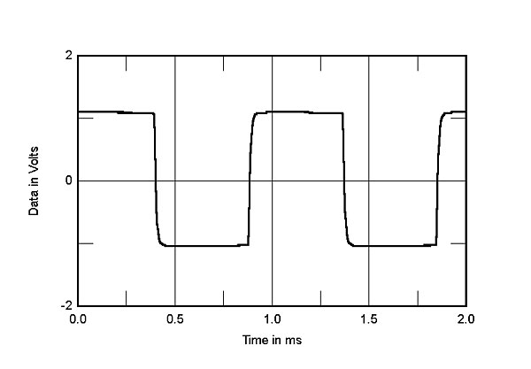
The MOSFET amplifier module's input impedance was a reasonably high 40k ohms. Its output impedance was low, at 0.12 ohm at 20Hz, 0.084 ohm at 1kHz, and 0.086 ohm at 20kHz, which gave a very small variation in response with our standard simulated loudspeaker (fig.16, gray trace). Fig.16, taken with the Tubestage driving the amplifier module and the RVC set to "63," shows excellent channel matching and a wide small-signal bandwidth. However, when I repeated this test with the AVC also set to "63," a 13dB peak at 34kHz appeared. The height of this peak didn't appear to be affected by the volume-control setting, though the frequency increased at lower settings. Fig.17, for example, compares the LIO's overall frequency response, measured at the speaker terminals, with both the RVC and AVC set to "43." The RVC's ultrasonic response (blue and red traces) is identical to what it was in fig.16, with a –3dB point at 75kHz, while with the AVC, the 13dB peak now lies at 80kHz. The puzzle to me is that this ultrasonic peak with the AVC resulted in no overshoot or ringing with the LIO's squarewave response (fig.18). I did wonder if there was some sort of interaction between the AVC's transformers and the input of the Audio Precision test set, but then I remembered that this peak was also evident with the AVC feeding the LIO's headphone module.
I tested the MOSFET amplifier module in four setups: 1) with the RVC module and the Tubestage; 2) with the RVC and no Tubestage, using the little bypass module in the latter's place; 3) with the AVC, which replaces both the RVC and the Tubestage; and 4) without any volume-control module, which appears to send the selected input signal straight to the amplifier module. The maximum voltage gain at the speaker terminals into 8 ohms varied with each of these conditions: 33.4dB with the AVC, and a significantly lower 25.8dB with and without the RVC or Tubestage. Comparisons among these different volume control modules will be misleading unless the different gains are compensated for.
The MOSFET amplifier module's input impedance was a reasonably high 40k ohms. Its output impedance was low, at 0.12 ohm at 20Hz, 0.084 ohm at 1kHz, and 0.086 ohm at 20kHz, which gave a very small variation in response with our standard simulated loudspeaker (fig.16, gray trace). Fig.16, taken with the Tubestage driving the amplifier module and the RVC set to "63," shows excellent channel matching and a wide small-signal bandwidth. However, when I repeated this test with the AVC also set to "63," a 13dB peak at 34kHz appeared. The height of this peak didn't appear to be affected by the volume-control setting, though the frequency increased at lower settings. Fig.17, for example, compares the LIO's overall frequency response, measured at the speaker terminals, with both the RVC and AVC set to "43." The RVC's ultrasonic response (blue and red traces) is identical to what it was in fig.16, with a –3dB point at 75kHz, while with the AVC, the 13dB peak now lies at 80kHz. The puzzle to me is that this ultrasonic peak with the AVC resulted in no overshoot or ringing with the LIO's squarewave response (fig.18). I did wonder if there was some sort of interaction between the AVC's transformers and the input of the Audio Precision test set, but then I remembered that this peak was also evident with the AVC feeding the LIO's headphone module.


 The LIO is specified as being able to deliver 25Wpc into 8 ohms (14dBW) or 45Wpc into 4 ohms (13.5dBW). However, with our standard definition of clipping being when the THD+noise reaches 1%, the LIO didn't reach those powers under that condition. It clipped at 17Wpc into 8 ohms (12.3dBW, fig.20) and 30Wpc into 4 ohms (11.75dBW, fig.21). The LIO did meet its specified power into both impedances at 11% THD+N, however. Perhaps more significant is the level of THD+N at lower powers, which is fairly high. These graphs were taken with a signal frequency of 1kHz and the RVC driving the amplifier module; changing to the AVC or adding the Tubestage made no difference. But when I plotted how the THD+N percentage changed with frequency at a voltage level equivalent to 3Wpc into 8 ohms and 6Wpc into 4 ohms, it appears that the Tubestage itself contributes distortion at high frequencies. Fig.22 shows the variation in THD with the AVC, fig.23 with the Tubestage. In both cases, the THD level at moderate powers is high. Fortunately for the sound quality, the distortion is heavily second-harmonic in nature (fig.24, footnote 1), though plenty of higher-order harmonics are present, especially at low frequencies (fig.25). And given Herb Reichert's positive reaction to the LIO's sound when used as an integrated amplifier with the AVC, it is perhaps not surprising that its high-frequency intermodulation performance in this configuration, measured at a level close to visible waveform clipping on the oscilloscope, was not too bad (fig.26).


 I was impressed by the concept underlying the Vinnie Rossi LIO, and its physical execution is stunning. But other than the RVC, moving-magnet Phonostage, and Digital modules, all of which offered good to excellent measured performance, there are problems with the other modules that bothered me. Of course, the benefit of the approach adopted by Vinnie Rossi with the LIO is that he can introduce running improvements to individual modules without requiring the owner replace the entire chassis.—John Atkinson
Footnote 1: See Art Dudley's "Listening" column in February 2015.
Fig.1 Vinnie Rossi LIO, Phonostage, response with RIAA correction: MM input (left channel blue, right red), MC input (left cyan, right magenta) (1dB/vertical div.).
Overload margins at low and middle frequencies were good for both MM and MC inputs, at 19dB (MM) and 17dB (MC), but the high-frequency overload margin was only okay for the MM input (10dB), and poor for the MC input (just 1.5dB). Distortion was a little higher than normal, though predominantly the subjectively innocuous second harmonic (fig.2). But even at the equivalent MM level of 1kHz at 5mV, high-frequency intermodulation was poor, with the difference component at 1kHz resulting from an equal mix of 19 and 20kHz tones lying at just –33dB (2.2%, fig.3).
Fig.2 Vinnie Rossi LIO, Phonostage (MM), spectrum of 1kHz sinewave, DC–10kHz, at 5mV input into 100k ohms (linear frequency scale).
Fig.3 Vinnie Rossi LIO, Phonostage (MM), HF intermodulation spectrum, DC–30kHz, 19+20kHz at 50mV input peak into 100k ohms (linear frequency scale).
Turning to the digital input module, I tested the USB input using my MacBook Pro running on battery power. Apple's USB Prober utility identified the module as "XMOS USB 2.0 Audio Out" and confirmed that it operated in the optimal isochronous asynchronous mode. The TosLink input accepted 24-bit data with sample rates up to 96kHz, the coaxial input 24 bits up to 192kHz, while the USB input accepted 32-bit integer data with sample rates up to 384kHz.
Fig.4 Vinnie Rossi LIO, digital input, Filter 1, impulse response at 44.1kHz (4ms time window).
Fig.5 Vinnie Rossi LIO, digital input, Filter 2, impulse response at 44.1kHz (4ms time window).
Fig.6 Vinnie Rossi LIO, digital input, Filter 1, wideband spectrum of white noise at –4dBFS (left channel blue, right cyan) and 19.1kHz tone at 0dBFS (left red, right magenta), with data sampled at 44.1kHz (20dB/vertical div.).
Fig.7 Vinnie Rossi LIO, digital input, Filter 1, frequency response at –12dBFS into 100k ohms with data sampled at: 44.1kHz (left channel green, right gray), 96kHz (left cyan, right magenta), 192kHz (left blue, right red) (0.5dB/vertical div.).
Fed first 16-bit data, then 24-bit data, each representing a dithered 1kHz tone at exactly –90dBFS, the drop in the noise floor with the increase in bit depth was just over 10dB (fig.8), implying resolution of almost 18 bits. This test was performed with TosLink data; I repeated the test with USB data and got identical results, indicating that the USB input does correctly handle hi-rez data. However, I was puzzled by the appearance of very low-level spuriae at 120Hz and its harmonics in this graph, given the hefty ultracapacitor power supply, which is charged with 24V DC by the outboard supply.
Fig.8 Vinnie Rossi LIO, digital input, waveform of undithered 1kHz sinewave at –90.31dBFS, 16-bit data (left channel blue, right red).
The LIO correctly handled 16- and 24-bit undithered data (figs.9 & 10), and offered low levels of harmonic distortion, with the second harmonic dominant at –80dB (0.01%, fig.11). Intermodulation distortion (not shown) was also very low. Tested for its rejection of word-clock jitter, the module's USB input performed very well, as expected. There are no jitter-related sidebands present with 16-bit/44.1kHz J-Test data (fig.12), though there is an odd rise in the noise floor either side of the primary tone. This was also present with 24-bit J-Test data. However, with 16- and 24-bit TosLink data, sidebands appeared at ±60, ±120, and ±180Hz (fig.13). This, too, puzzled me—there should be no AC-line–related components present at all, given the LIO's massively stiff power supply.
Fig.9 Vinnie Rossi LIO, digital input, waveform of undithered 1kHz sinewave at –90.31dBFS, 24-bit data (left channel blue, right red).
Fig.10 Vinnie Rossi LIO, digital input, spectrum with noise and spuriae of dithered 1kHz tone at –90dBFS with: 16-bit data (left channel cyan, right magenta), 24-bit data (left blue, right red) (20dB/vertical div.).
Fig.11 Vinnie Rossi LIO, digital input, spectrum of 50Hz sinewave, DC–1kHz, at 0dBFS into 100k ohms (left channel blue, right red; linear frequency scale).
Fig.12 Vinnie Rossi LIO, digital input, high-resolution jitter spectrum of analog output signal, 11.025kHz at –6dBFS, sampled at 44.1kHz with LSB toggled at 229Hz: 16-bit data from MacBook Pro via USB (left channel blue, right red). Center frequency of trace, 11.025kHz; frequency range, ±3.5kHz.
Fig.13 Vinnie Rossi LIO, digital input, high-resolution jitter spectrum of analog output signal, 11.025kHz at –6dBFS, sampled at 44.1kHz with LSB toggled at 229Hz: 16-bit data from AP SYS2722 via Toslink (left channel blue, right red). Center frequency of trace, 11.025kHz; frequency range, ±3.5kHz.
The LIO's headphone-amplifier module follows whichever volume-control option has been fitted, and is connected in parallel with the Variable preamp outputs and the input of the MOSFET amplifier module, if fitted. It offered a maximum gain of 13dB with the AVC and inverted signal polarity. The output impedance was a suitably low 6 ohms at low and middle frequencies, though this rose to 18.5 ohms at 20kHz. Though the audioband response was flat and well matched between channels, I was surprised to find a 10dB peak at 35kHz with the AVC feeding the headphone module (fig.14).
Fig.14 Vinnie Rossi LIO, Headphone output, Autoformer Volume Control set to "43" frequency response at 1V into 600 ohms ((left blue, right red; 2dB/vertical div.).
Fig.15 Vinnie Rossi LIO, Tubestage, Resistor Volume Control and Tubestage, volume control set to maximum, spectrum of 50Hz sinewave, DC–1kHz, at 300mV into 100k ohms (linear frequency scale).
Fig.16 Vinnie Rossi LIO, Resistor Volume Control and Tubestage, volume control set to maximum, frequency response at 2.83V into: simulated loudspeaker load (gray), 8 ohms (left channel blue, right red), 4 ohms (left cyan, right magenta), 2 ohms (green) (2dB/vertical div.).
Fig.17 Vinnie Rossi LIO, Resistor Volume Control and Tubestage, volume control set to "43" (left channel blue, right red), Autoformer Volume Control set to "43" (left cyan, right magenta): frequency response at 2.83V into 8 ohms (2dB/vertical div.).
Fig.18 Vinnie Rossi LIO, Autoformer Volume Control set to maximum: small-signal, 1kHz squarewave into 8 ohms.
The amplifier module's channel separation was good, at >90dB between 1 and 3kHz, though it dropped to 64dB at 100Hz and 78dB at 20kHz. The unweighted, wideband S/N ratio, measured with the line input shorted and the AVC set to "63," was a good 77.3dB ref. 2.83V into 8 ohms. This improved to 91.3dB when the measurement bandwidth was restricted to 22Hz–22kHz, and to 94.3dB when A-weighted. Again I was puzzled by the appearance of low-level spuriae at 60Hz and its harmonics in the amplifier's output when it drove 1kHz at 1Wpc into 8 ohms (fig.19). The AVC was connected for this measurement, and perhaps the transformers were picking up radiated magnetic interference from the computer that runs the Audio Precision software. However, moving the computer made no difference.
Fig.19 Vinnie Rossi LIO, Autoformer Volume Control set to maximum: spectrum of 1kHz sinewave, DC–1kHz, at 1W into 8 ohms (linear frequency scale).
Fig.20 Vinnie Rossi LIO, Resistor Volume Control set to maximum: distortion (%) vs 1kHz continuous output power into 8 ohms.
Fig.21 Vinnie Rossi LIO, Resistor Volume Control set to maximum: distortion (%) vs 1kHz continuous output power into 4 ohms.
Fig.22 Vinnie Rossi LIO, Autoformer Volume Control set to maximum, THD+N (%)vs frequency at 4.9V into: 8 ohms (left channel blue, right red), 4 ohms (left cyan, right magenta).
Fig.23 Vinnie Rossi LIO, Resistor Volume Control and Tubestage, volume control set to maximum, THD+N (%) vs frequency at 4.9V into: 8 ohms (left channel blue, right red), 4 ohms (left cyan, right magenta).
Fig.24 Vinnie Rossi LIO, Autoformer Volume Control set to maximum, 1kHz waveform at 6W into 4 ohms, 0.47% THD+N (top): distortion and noise waveform with fundamental notched out (bottom, not to scale).
Fig.25 Vinnie Rossi LIO, Resistor Volume Control and Tubestage, volume control set to maximum: spectrum of 50Hz sinewave, DC–1kHz, at 3W into 8 ohms (linear frequency scale).
Fig.26 Vinnie Rossi LIO, Autoformer Volume Control set to maximum: HF intermodulation spectrum, DC–24kHz, 19+20kHz at 3W peak into 8 ohms (linear frequency scale).
Finally, as the LIO is powered by the capacitor supply, it will run only a certain length of time from one bank of capacitors before switching to the other. With the LIO driving 1kHz at 1Wpc into 8 ohms and one capacitor bank newly charged, the supply voltage dropped from 22.9 to 19V in exactly three minutes, at which point the LIO automatically switched to the second bank, now freshly charged, with a just-audible click.
Footnote 1: See Art Dudley's "Listening" column in February 2015.


