Sidebar 3: Measurements
I tested the Yamaha A-S3200 with my Audio Precision SYS2722 system (see the January 2008 "As We See It"). I first preconditioned the amplifier by following the CEA's recommendation of operating it at one-eighth the specified power into 8 ohms for 30 minutes. At the end of that time, the top panel was warm, at 101.4°F (38.6°C). I subsequently performed my usual thermal stress test by running the amplifier at one-third power into 8 ohms for an hour. The Yamaha's top panel was only a little warmer than before, at 109.8°F (43.3°C). The A-S3200 appears to operate its output devices with a relatively high amount of bias current, but it has sufficient heatsinking capacity for its power.
Examined first at its single-ended line inputs, the Yamaha offered a high maximum gain of 43.4dB into 8 ohms. The balanced line inputs offered 43.5dB, with these inputs' attenuation switches reducing the gain by 6dB, as specified. The gain at the preamplifier output was a high 13.5dB for both sets of inputs. The maximum gain at the headphone output was 17.8dB with the trim switch set to "0." Setting the trim to "–6" reduced the headphone gain by 6dB; setting it to "+6" and "+12" increased the gain by 6dB and 12dB, respectively. The amplifier preserved absolute polarity at all three sets of outputs—loudspeaker, headphone, and preamplifier—for unbalanced, line-level input signals and for the balanced inputs when set to "Phase Normal," which corresponds to pin 2 of the XLR jack carrying the balanced signal's "hot" phase.
The unbalanced line input impedance was usefully high, at 39k ohms at low and middle frequencies, dropping inconsequentially to 28k ohms at the top of the audioband. As expected, the balanced input impedances were twice the unbalanced values, except at 20kHz, where it was a still-high 71k ohms. The headphone output impedance was a reasonably low 4 ohms at 20Hz and 1kHz, rising slightly to 6.9 ohms at 20kHz. The output impedance at the preamplifier output was a high 1440 ohms at high and middle frequencies, rising to 1570 ohms in the low bass.
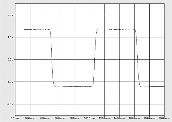
The output impedance at the loudspeaker terminals was low, at 0.09 ohms at 20Hz and 1kHz, rising to 0.14 ohm at 20kHz. (The figures include the series impedance of 6' of spaced-pair loudspeaker cable.) The modulation of the amplifier's frequency response, due to the Ohm's law interaction between this source impedance and the impedance of our standard simulated loudspeaker, was therefore negligible, at ±0.15dB (fig.1, gray trace). The response into an 8 ohm resistive load (fig.1, blue and red traces) was flat to 20kHz and down by 2.75dB at 200kHz, which correlates with accurate reproduction of a 10kHz squarewave (fig.2)—commendably, there was no overshoot or ringing with the squarewave response. Fig.1 was taken with the volume control set to its maximum and the balance control centered. A small, 0.1dB, channel imbalance can be seen in this graph. This imbalance and the frequency response didn't change at lower settings of the volume control.


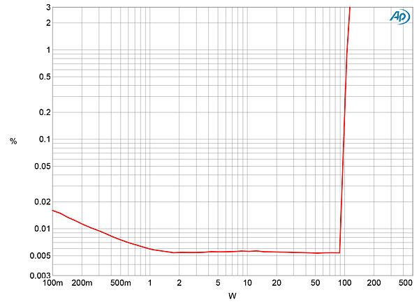
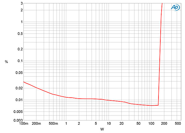
 With both channels driven, the A-S3200 exceeded its specified maximum continuous power into 8 ohms of 100Wpc (20dBW), clipping (defined by 1% THD+noise) at 110Wpc (20.4dBW, fig.6). Into 4 ohms, the Yamaha clipped at 168Wpc (19.25dBW, fig.7) compared with the specification's 150W (18.75dBW). The distortion was very low before actually clipping into either load and increased only slightly into 4 ohms (fig.8, cyan and magenta traces) compared with 8 ohms (blue and red traces). Interestingly, when I repeated this test into 2 ohms, which for logistical reasons I could only do with one channel, the distortion was lower (gray trace) than it had been into 4 ohms with both channels driven (cyan trace).


 In MM mode, the maximum gain at the phono inputs was 78.4dB at the loudspeaker terminals, 58.6dB at the headphone output, and 49.4dB at the preamplifier output. In MC mode, these maximum gains were 24dB higher. To avoid overloading the A-S3200's power amplifier stage when I measured the phono input, I turned off the speaker outputs with the front-panel switch. I performed the phono stage measurements with the volume control set to its maximum at either the preamplifier output or at the headphone output. (Plugging a ¼" jack plug into the headphone output also mutes the loudspeaker outputs.)
Set to MM, the phono input preserved absolute polarity at all three sets of outputs, though it inverted polarity when set to MC. With the phono stage set to MM, the input impedance was 45k ohms at 20Hz and 1kHz, 35k ohms at 20kHz. The MC mode's input impedance was 48 ohms across the audioband. The A-S3200's RIAA correction (fig.12) was well-matched between the channels but had a broad, 0.5dB-high plateau in the treble. There was also a peak of 0.5dB in the bass before the usual low-frequency rolloff reached –2dB at 10Hz.
In MM mode, the maximum gain at the phono inputs was 78.4dB at the loudspeaker terminals, 58.6dB at the headphone output, and 49.4dB at the preamplifier output. In MC mode, these maximum gains were 24dB higher. To avoid overloading the A-S3200's power amplifier stage when I measured the phono input, I turned off the speaker outputs with the front-panel switch. I performed the phono stage measurements with the volume control set to its maximum at either the preamplifier output or at the headphone output. (Plugging a ¼" jack plug into the headphone output also mutes the loudspeaker outputs.)
Set to MM, the phono input preserved absolute polarity at all three sets of outputs, though it inverted polarity when set to MC. With the phono stage set to MM, the input impedance was 45k ohms at 20Hz and 1kHz, 35k ohms at 20kHz. The MC mode's input impedance was 48 ohms across the audioband. The A-S3200's RIAA correction (fig.12) was well-matched between the channels but had a broad, 0.5dB-high plateau in the treble. There was also a peak of 0.5dB in the bass before the usual low-frequency rolloff reached –2dB at 10Hz.
 Channel separation via the phono input was an excellent 90dB in both directions in the low treble. The phono input's noise performance in MM mode was also excellent, with unweighted audioband signal/noise ratios (ref. 1kHz at 5mV input signal) of 78dB (average of both channels). The ratios improved by 10dB when A-weighted. Set to MC, the ratios were all 9–10dB lower than in MM mode, but these are still excellent given this mode's higher-than-usual gain. This is a low-noise phono stage.
The A-S3200's phono input offered good overload margins in MM mode, at around 17dB ref. 1kHz at 5mV across the band, but a lower 12.5dB ref. 1kHz at 500µV in MC mode. Distortion at typical recorded levels was low, primarily consisting of the third and fifth harmonics (fig.13). Intermodulation distortion via the Yamaha's phono input was also very low.
Channel separation via the phono input was an excellent 90dB in both directions in the low treble. The phono input's noise performance in MM mode was also excellent, with unweighted audioband signal/noise ratios (ref. 1kHz at 5mV input signal) of 78dB (average of both channels). The ratios improved by 10dB when A-weighted. Set to MC, the ratios were all 9–10dB lower than in MM mode, but these are still excellent given this mode's higher-than-usual gain. This is a low-noise phono stage.
The A-S3200's phono input offered good overload margins in MM mode, at around 17dB ref. 1kHz at 5mV across the band, but a lower 12.5dB ref. 1kHz at 500µV in MC mode. Distortion at typical recorded levels was low, primarily consisting of the third and fifth harmonics (fig.13). Intermodulation distortion via the Yamaha's phono input was also very low.
 I got a twinge of nostalgia when I unpacked the Yamaha A-S3200, as its styling evoked memories of Yahama's "Natural Sound" receivers from the 1970s. Its performance on the test bench indicated generally excellent audio engineering, though the fact that it doesn't double its maximum power when the load impedance halves suggests that it shouldn't be used with loudspeakers with impedances that drop much below 4 ohms.—John Atkinson
Fig.1 Yamaha A-S3200, volume control set to maximum, frequency response at 2.83V into: simulated loudspeaker load (gray), 8 ohms (left channel blue, right red) 4 ohms (left cyan, right magenta), (left green) (0.5dB/vertical div.).
Fig.2 Yamaha A-S3200, small-signal 10kHz squarewave into 8 ohms.
Fig.3 shows the effect of the treble bass controls set to their maximum and minimum positions compared with them set to their central positions, where the tone control circuitry is bypassed. The maximum boost and cut is close to 10dB. Channel separation (not shown) was excellent, at >100dB in both directions below 2kHz, and still 80dB at the top of the audioband. The Yamaha's unweighted signal/noise ratio, taken with the line input shorted to ground but the volume control at its maximum, was 70dB ref. 2.83V into 8 ohms (average of both channels). This ratio improved to 78.5dB when the measurement bandwidth was restricted to the audioband, and to 82dB when A-weighted. The background noise included spuriae at 60Hz, and its odd-order harmonics, which will be due to magnetic interference from the power transformer, and full-wave–rectified, supply-related spuriae at 120Hz and its harmonics (fig.4). These are all low in level. The random noise floor components seen in this graph were lower in level at lower settings of the volume control (fig.5).
Fig.3 Yamaha A-S3200, frequency response at 1V into 8 ohms with treble and bass controls set ot their maximum and minimum and switched out of circuit (left channel blue, right red) (2.5dB/vertical div.).
Fig.4 Yamaha A-S3200, volume control set to maximum, spectrum of 1kHz sinewave, DC–1kHz, at 1W into 8 ohms (left channel blue, right red; linear frequency scale).
Fig.5 Yamaha A-S3200, volume control set to "12:00," spectrum of 1kHz sinewave, DC–1kHz, at 1W into 8 ohms (left channel blue, right red; linear frequency scale).
Fig.6 Yamaha A-S3200, distortion (%) vs 1kHz continuous output power into 8 ohms.
Fig.7 Yamaha A-S3200, distortion (%) vs 1kHz continuous output power into 4 ohms.
Fig.8 Yamaha A-S3200, THD+N (%) vs frequency at 15.5V into: 8 ohms (left channel blue, right red), 4 ohms (left cyan, magenta), 2 ohms (left, gray).
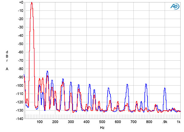
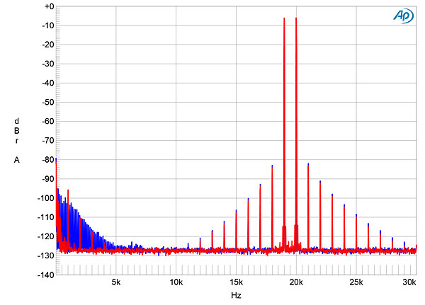
The distortion was predominantly the subjectively benign third harmonic (fig.9), but higher odd-order harmonics are present at lower levels, particularly in the left channel (fig.9, blue trace). Some second harmonic is also present, and this was a little higher in the right channel, at –90dB (fig.10, red trace), than in the left channel. When the A-S3200 drove an equal mix of 19 and 20kHz tones at 30W into 8 ohms (fig.11), the second-order difference product at 1kHz lay at a low –96dB (0.0015%), and higher-order intermodulation products were all below –80dB (0.01%).
Fig.9 Yamaha A-S3200, 1kHz waveform at 15W into 8 ohms, 0.009% THD+N (top); distortion and noise waveform with fundamental notched out (bottom, not to scale).
Fig.10 Yamaha A-S3200, spectrum of 50Hz sinewave, DC–1kHz, at 30W into 8 ohms (left channel blue, right red; linear frequency scale).
Fig.11 Yamaha A-S3200, HF intermodulation spectrum, DC–30kHz, 19+20kHz at 30W peak into 8 ohms (left channel blue, right red; linear frequency scale).
Fig.12 Yamaha A-S3200, phono input, MM mode, response with RIAA correction (left channel blue, right red) (0.5dB/vertical div.).
Fig.13 Yamaha A-S3200, phono input, MM mode, spectrum of 1kHz sinewave, DC–10kHz, at 1mV input (left channel blue, right red; linear frequency scale).


