Comments from Bob Stuart
This is an interesting article, my thanks to John Atkinson for the opportunity to clarify.
The article shows measurements of A/D and D/A cascades; however, these are not measurements of MQA. The diagram below may clarify.
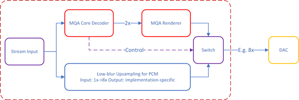 The diagram shows the structure of a typical MQA Decoder (dotted box), connected to a paired D/A converter. There are two signal paths. In the upper path, when an incoming MQA stream is detected, the MQA decode proceeds, first to unfold to the 'MQA Core' signal (typically at 2x, ie, 88.2 or 96kHz) and then to the MQA Renderer. Inter alia, the Renderer includes reconstruction filtering which is directly controlled by the MQA Studio Encoder and which is also customized per platform, in order that the convolution of the Renderer + DAC
+ analog output filtering gives the correct, authenticated, audio result. The Renderer operation can be configured by the product designer to output either the Original Sample Rate or a higher rate (up to 16x) to bypass some or all of the upsampling filters inside a delta-sigma DAC itself (footnote 1)
When the signal is not MQA, we provide a low-blur, minimum-phase, high-guality upsampling array that will allow signals between lx and 16x to be passed seamlessly to the DAC (lower path in the diagram). This upsampling design is based on extremely careful design and extensive listening tests, gives very high-guality results and has been preferred by many makers. Most implementations use the architecture shown above, but some set makers use a separate path to the DAC for PCM because they have a specific process or product ethos to maintain.
Why is the Decoder built this way? Fundamentally this architecture gives a better user experience. Many DACs cannot switch sample rate instantaneously. MQA is unique in that the physical sample rate increases as the Decoder unfolds the "Origami." If an incoming stream comprises a mixed playlist of songs in PCM and MQA, or if the listener is skipping around in a song or cross-fading between streams, then the MQA Decoder smoothly mediates and prevents pauses, gaps, glitches, clicks etc by seamlessly switching the listener to the upsampler
chain whenever the stream is not authenticated.
So, there are two distinct pathways depending on whether the incoming signal is MQA or PCM (footnote 2).
MQA itself has its roots in a hierarchical system based on B-splines but with enhancements to ensure flat frequency response and to minimize aliasing. The encoder and decoder responses are complementary and matched to each other; the characteristic of each and of their cascade is adjusted according to the source
content and is further optimised for listeners with and without decoders.
Although rooted in splines, the final end-to-end (analog-to-analog) response of MQA is modeled on natural dispersion, eg, such as when sound travels though air. MQA also exploits the causal nature and energy distribution of natural and instrumental sounds. The music we enjoy never fully occupies a rectangular amplitude/frequency channel, which is one of the ways in which we can improve on the sampling process. However, the fact that this system is responsive to the source, means there is no such thing as "the MQA filter"
and the Encoder has wide freedom to optimize the end-to-end result.
In John Atkinson's experiments, the signals fed into the Brooklyn were PCM and not MQA, and therefore the MQA reconstruction (including the Rendering) filters were never engaged. So, in his graphs, what is seen is the
convolution of the test signal and a minimum-phase, tight-time-domain-constrained upsampling chain taking 44.1 to 352.8kHz or 96 to 384kHz with ripple-free response and less than 50mB droop at 20kHz. Every effort
is made in the MQA Decoder to maximise the quality of PCM.
It isn't surprising therefore that when the test signal is a minimum-phase pulse, with (as dCS) or without (as Ayre) response flattening, that the MQA Decoder path has presented a very tidy result to the DAC.—Bob Stuart, MQA Ltd.
The diagram shows the structure of a typical MQA Decoder (dotted box), connected to a paired D/A converter. There are two signal paths. In the upper path, when an incoming MQA stream is detected, the MQA decode proceeds, first to unfold to the 'MQA Core' signal (typically at 2x, ie, 88.2 or 96kHz) and then to the MQA Renderer. Inter alia, the Renderer includes reconstruction filtering which is directly controlled by the MQA Studio Encoder and which is also customized per platform, in order that the convolution of the Renderer + DAC
+ analog output filtering gives the correct, authenticated, audio result. The Renderer operation can be configured by the product designer to output either the Original Sample Rate or a higher rate (up to 16x) to bypass some or all of the upsampling filters inside a delta-sigma DAC itself (footnote 1)
When the signal is not MQA, we provide a low-blur, minimum-phase, high-guality upsampling array that will allow signals between lx and 16x to be passed seamlessly to the DAC (lower path in the diagram). This upsampling design is based on extremely careful design and extensive listening tests, gives very high-guality results and has been preferred by many makers. Most implementations use the architecture shown above, but some set makers use a separate path to the DAC for PCM because they have a specific process or product ethos to maintain.
Why is the Decoder built this way? Fundamentally this architecture gives a better user experience. Many DACs cannot switch sample rate instantaneously. MQA is unique in that the physical sample rate increases as the Decoder unfolds the "Origami." If an incoming stream comprises a mixed playlist of songs in PCM and MQA, or if the listener is skipping around in a song or cross-fading between streams, then the MQA Decoder smoothly mediates and prevents pauses, gaps, glitches, clicks etc by seamlessly switching the listener to the upsampler
chain whenever the stream is not authenticated.
So, there are two distinct pathways depending on whether the incoming signal is MQA or PCM (footnote 2).
MQA itself has its roots in a hierarchical system based on B-splines but with enhancements to ensure flat frequency response and to minimize aliasing. The encoder and decoder responses are complementary and matched to each other; the characteristic of each and of their cascade is adjusted according to the source
content and is further optimised for listeners with and without decoders.
Although rooted in splines, the final end-to-end (analog-to-analog) response of MQA is modeled on natural dispersion, eg, such as when sound travels though air. MQA also exploits the causal nature and energy distribution of natural and instrumental sounds. The music we enjoy never fully occupies a rectangular amplitude/frequency channel, which is one of the ways in which we can improve on the sampling process. However, the fact that this system is responsive to the source, means there is no such thing as "the MQA filter"
and the Encoder has wide freedom to optimize the end-to-end result.
In John Atkinson's experiments, the signals fed into the Brooklyn were PCM and not MQA, and therefore the MQA reconstruction (including the Rendering) filters were never engaged. So, in his graphs, what is seen is the
convolution of the test signal and a minimum-phase, tight-time-domain-constrained upsampling chain taking 44.1 to 352.8kHz or 96 to 384kHz with ripple-free response and less than 50mB droop at 20kHz. Every effort
is made in the MQA Decoder to maximise the quality of PCM.
It isn't surprising therefore that when the test signal is a minimum-phase pulse, with (as dCS) or without (as Ayre) response flattening, that the MQA Decoder path has presented a very tidy result to the DAC.—Bob Stuart, MQA Ltd.
Footnote 1: It is commonly found that minimizing upsampling inside the DAC is beneficial. In this example diagram (and in Brooklyn), the DAC is always fed at 8x rate (ie, 352.8 or 384kHz). Footnote 2: This is also the case in the Brooklyn—when it has MQA enabled. Brooklyn allows the MQA decoder to be disabled, in which case the PCM path uses the native upsampling in the ESS DAC chip.
The diagram shows the structure of a typical MQA Decoder (dotted box), connected to a paired D/A converter. There are two signal paths. In the upper path, when an incoming MQA stream is detected, the MQA decode proceeds, first to unfold to the 'MQA Core' signal (typically at 2x, ie, 88.2 or 96kHz) and then to the MQA Renderer. Inter alia, the Renderer includes reconstruction filtering which is directly controlled by the MQA Studio Encoder and which is also customized per platform, in order that the convolution of the Renderer + DAC
+ analog output filtering gives the correct, authenticated, audio result. The Renderer operation can be configured by the product designer to output either the Original Sample Rate or a higher rate (up to 16x) to bypass some or all of the upsampling filters inside a delta-sigma DAC itself (footnote 1)
When the signal is not MQA, we provide a low-blur, minimum-phase, high-guality upsampling array that will allow signals between lx and 16x to be passed seamlessly to the DAC (lower path in the diagram). This upsampling design is based on extremely careful design and extensive listening tests, gives very high-guality results and has been preferred by many makers. Most implementations use the architecture shown above, but some set makers use a separate path to the DAC for PCM because they have a specific process or product ethos to maintain.
Footnote 1: It is commonly found that minimizing upsampling inside the DAC is beneficial. In this example diagram (and in Brooklyn), the DAC is always fed at 8x rate (ie, 352.8 or 384kHz). Footnote 2: This is also the case in the Brooklyn—when it has MQA enabled. Brooklyn allows the MQA decoder to be disabled, in which case the PCM path uses the native upsampling in the ESS DAC chip.


