Sidebar 3: Measurements
I tested the Parasound Halo A 21+ with my Audio Precision SYS2722 system (see the January 2008 "As We See It"). I preconditioned the amplifier by operating it at one-third the specified power into 8 ohms for an hour. (With a class-AB output stage, one-third power results in the maximum dissipation in the output devices.) At the end of this time, the side-mounted heatsinks were very hot, at 162.8°F (72.7°C). The top panel was also hot, at 116°F (46.7.1°C).
The Parasound's voltage gain into 8 ohms measured 29.2dB from the balanced inputs, 29.4dB from the unbalanced inputs. In bridged-mono mode, the gain was 34.9dB into 8 ohms. The amplifier preserved absolute polarity (ie, was noninverting) with both balanced and unbalanced input signals and with the right channel used as the input in bridged-mono mode, with the outputs taken from the two positive loudspeaker terminals as described in the manual. The balanced input impedance was high at 90k ohms at 20Hz and 1kHz, dropping to a still-high 84k ohms at 20kHz. The unbalanced input impedance was 46k ohms at low and middle frequencies, 37k ohms at the top of the audioband.
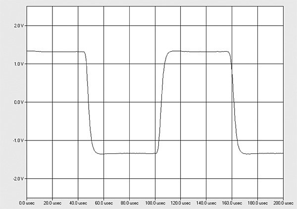
The Parasound's output impedance was a very low 0.077 ohm at 20Hz and 1kHz, increasingly slightly to 0.1 ohm at 20kHz. (These figures include the series impedance of 6' of loudspeaker cable.) The modulation of the amplifier's frequency response, due to the Ohm's law interaction between this source impedance and the impedance of our standard simulated loudspeaker, was therefore minuscule, at ±0.1dB (fig.1, gray trace). The response into an 8 ohm resistive load (fig.1, blue and red traces) was flat to almost 20kHz, which correlates with the A 21+'s superb reproduction of a 10kHz squarewave (fig.2). Fig.1 was taken with the balanced inputs; the response with the unbalanced input was identical, though in bridged-mono mode, the output at 20kHz was down by a still-trivial 0.25dB, due to the doubling of the amplifier's output impedance in this mode. A slight 0.35dB channel imbalance in favor of the left channel (blue and cyan traces) can be seen in fig.1, even though the level controls for the two channels had both been set to their maximum positions.

 Parasound specifies the A 21+ as delivering 300W into 8 ohms (24.8dBW) with both channels driven and 500W into 4 ohms (24dBW). Using our definition of clipping, which is when the output's percentage of THD+noise reaches 1%, the Parasound easily exceeded its specified powers with both channels driven with a 1kHz signal. It clipped at 400Wpc into 8 ohms (26dBW, fig.4) and at 620Wpc into 4 ohms (24.9dBW, fig.5). The maximum power into 2 ohms with one channel driven was 900W (23.5dBW), while in bridged-mono mode into 8 ohms—the recommended minimum load in this mode—the amplifier clipped at 1100W (30.4dBW).


 The Parasound A 21+ offers a lot of low-distortion power and isn't fazed by impedances as low as 2 ohms.—John Atkinson
Fig.1 Parasound A21+, frequency response at 2.83V into: simulated loudspeaker load (gray), 8 ohms (left channel blue, right red), 4 ohms (left cyan, right magenta), 2 ohms (green) (1dB/vertical div.).
Fig.2 Parasound A21+, small-signal 10kHz squarewave into 8 ohms.
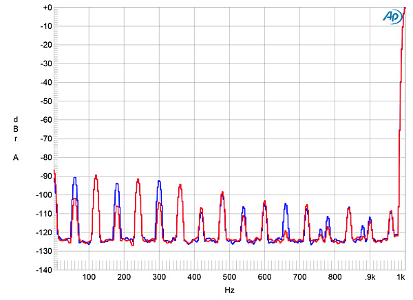
Channel separation was excellent, at >90dB in both directions below 2kHz, declining to a still-good 72dB at the top of the audioband. Measured with the unbalanced inputs shorted to ground, the amplifier's unweighted, wideband signal/noise ratio was 78.1dB ref. 1W into 8 ohms (average of both channels), this ratio improving to 88.7dB when the measurement was A-weighted. Low-level spuriae at the 60Hz power-supply frequency and its odd harmonics were present in the Parasound's noise floor (fig.3). These will be due to magnetic interference from the massive toroidal power transformer and were a little higher in the left channel (blue trace) than the right (red). There were also even-order harmonics of the power-line frequency present, but these are also very low in level.
Fig.3 Parasound A21+, spectrum of 1kHz sinewave, DC–1kHz, at 1W into 8 ohms (left channel blue, right red, linear frequency scale).
Fig.4 Parasound A21+, distortion (%) vs 1kHz continuous output power into 8 ohms.
Fig.5 Parasound A21+, distortion (%) vs 1kHz continuous output power into 4 ohms.
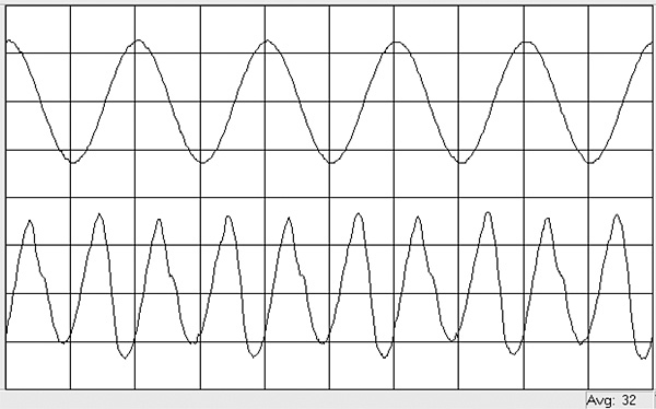
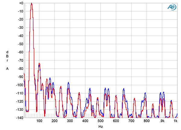
The shape of the traces in figs.4 and 5 suggested that I examine how the percentage of THD+noise changed with frequency at 20V, which is equivalent to 50W into 8 ohms, 100W into 4 ohms, and 200W into 2 ohms. The THD+N was very low in the midrange into 8, 4, and 2 ohms (fig.6) but rose at higher frequencies. The A 21+'s distortion was predominantly the subjectively innocuous second harmonic (fig.7), and higher harmonics are all very low in level (fig.8). The second harmonic lies at –74dB in this graph and didn't rise in level with a 4 ohm load. When the amplifier drove an equal mix of 19 and 20kHz tones at 50W into 8 ohms (fig.9), the second-order difference product at 1kHz lay at a very low –86dB (0.005%), and higher-order intermodulation products were even lower in level. Again, the levels of the distortion harmonics didn't rise when I kept the output voltage the same but reduced the load impedance to 4 ohms.
Fig.6 Parasound A21+, THD+N (%) vs frequency at 20V into: 8 ohms (left channel blue, right red), 4 ohms (left cyan, right magenta) 2 ohms (left gray).
Fig.7 Parasound A21+, 1kHz waveform at 25W into 8 ohms, 0.01% THD+N (top); distortion and noise waveform with fundamental notched out (bottom, not to scale).
Fig.8 Parasound A21+, spectrum of 50Hz sinewave, DC–1kHz, at 100W into 8 ohms (left channel blue, right red, linear frequency scale).
Fig.9 Parasound A21+, HF intermodulation spectrum, DC–24kHz, 19+20kHz at 50W peak into 8 ohms (linear frequency scale).


