Sidebar 3: Measurements
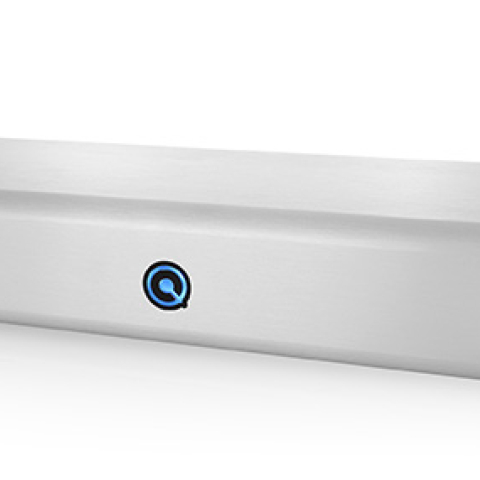
I measured the BSG qøl Signal Completion Stage with Stereophile's loan sample of the top-of-the-line Audio Precision SYS2722 system (see www.ap.com and the January 2008 "As We See It"). The BSG was non-inverting from all inputs to all outputs, in both active and bypass modes, with the XLR jacks wired with pin 2 positive. The input impedance was usefully higher than specified, at 18k ohms single-ended and 41k ohms balanced. The balanced output impedance was to specification, at 53 ohms at all audio frequencies, while the unbalanced output impedance was much lower, at 1 ohm.
With its matrixing circuitry, the Signal Completion Stage's voltage gain depended on the input signal configuration. With just one channel driven from an unbalanced input, the gain was a high 10.6dB from that channel's balanced output, and 6dB lower from the unbalanced outputs. With both channels equally driven from an unbalanced input but with the right channel in antiphase to the left (L–R), the gain was even higher, at 12.8dB balanced and 6.8dB unbalanced. However, when both input channels were in phase (L+R), the gain dropped to 7.8dB balanced, 1.8dB unbalanced. For balanced input to balanced output, all of these gains were reduced by 6dB.
The BSG had a wide frequency response, its high-frequency output dropping by 0.5dB at 50kHz into 100k ohms, with excellent channel matching (fig.1, blue and red traces). While the output dropped to 600 ohms (fig.1, cyan and magenta traces), the high-frequency extension was not affected. This graph was taken with an L+R input signal. Muting the right input gave the responses shown in fig.2. The left-channel output (blue trace) has risen by 2.82dB, but there is now an antiphase output at –8.1dB in the right-channel output. This suggests that the multiplying factors applied to the Sum and Difference signals in the matrix are slightly different from the Golden Ratio's 1.618 mentioned in the BSG patent, which, by my calculations, would give an antiphase signal in the undriven channel's output 12.5dB lower than the driven channel's, rather than the measured 10.9dB.

 Turning to the BSG's performance when used as a line stage, the matrixing circuitry rendered moot conventional measurement of channel separation. The unweighted, wideband signal/noise ratio, ref. 1V output with the input short-circuited, was 72.9dB left and 72.0dB right, these figures improving to 85.3 and 83.0dB, respectively, when A-weighted. Fig.3 shows how the THD+noise percentage in the Signal Completion Stage's balanced output varied with voltage into 100k ohms. The output circuitry clips at a high 19V, while the downward slope of the trace up to the clipping point reveals that if there is any distortion in the BSG's output, it is buried in the noise. Into 600 ohms (not shown), the clipping level was a still-high 16V, suggesting that the Signal Completion Stage has a beefy output stage; again, any distortion present was beneath the noise floor.


Fig.1 BSG qøl Signal Completion Stage, L+R input signal, balanced frequency response at 1V into: 100k ohms (left channel blue, right red), 600 ohms (left cyan, right magenta) (0.25dB/vertical div.).
Fig.2 BSG qøl Signal Completion Stage, L input signal, balanced frequency response at 1V into 100k ohms (left channel blue, right red) (1dB/vertical div.).
These measurements were all taken with sinewave signals, which, with a product such as this, do not truly represent what will happen with music. I therefore played the pink-noise track from Stereophile's Test CD 2 (Stereophile STPH004-2), the first half of which is a dual-mono signal (L+R); the second half has noise that is completely uncorrelated between the two channels. These two noise signals represent the two extremes that will be presented to the qøl processing; the uncorrelated signal was reproduced 3.4dB higher in level than the correlated noise. With music signals, which will have an interchannel correlation somewhere between these two extremes, there will always, therefore, be an increase in level of up to 3.4dB when the qøl signal processing is engaged, which makes A/B comparisons difficult.
Fig.3 BSG qøl Signal Completion Stage, balanced distortion (%) vs 1kHz output voltage into 100k ohms.
I examined how the THD+N percentage changed with frequency at a level, 2.5V, close to the maximum the BSG will be required to deliver in practical use. I haven't shown the result because it was flat with frequency and obviously just noise. As with the measured S/N ratios, the right channel was a little noisier than the left. Fig.4 reveals that this was due to some very low-level power-supply components in that channel. This graph was taken with the demanding 600-ohm load, and a trace of second-harmonic distortion can be seen in both channels. But at –112dB (0.00025%), this distortion is inconsequential. Intermodulation distortion (fig.5) was also very low.
Fig.4 BSG qøl Signal Completion Stage, balanced spectrum of 1kHz sinewave, DC–1kHz, at 2V into 600 ohms (left channel blue, right red; linear frequency scale).
Fig.5 BSG qøl Signal Completion Stage, balanced HF intermodulation spectrum, DC–30kHz, 19+20kHz at 2V into 100k ohms (left channel blue, right red; linear frequency scale).
Finally, although one of the BSG patents refers to a complicated phase-shifting and phase-layering circuit in addition to the matrixing, the Signal Completion Stage's impulse and step responses, and plots of phase and group delay (not shown), didn't indicate any phase shift, either for a single channel on its own or for a dual-mono signal.—John Atkinson